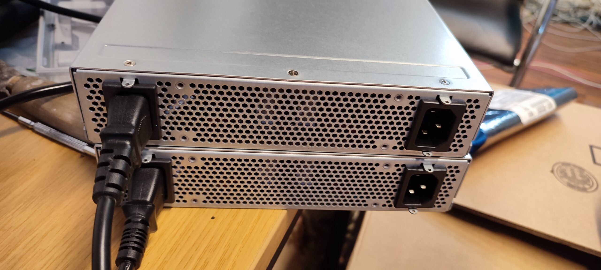
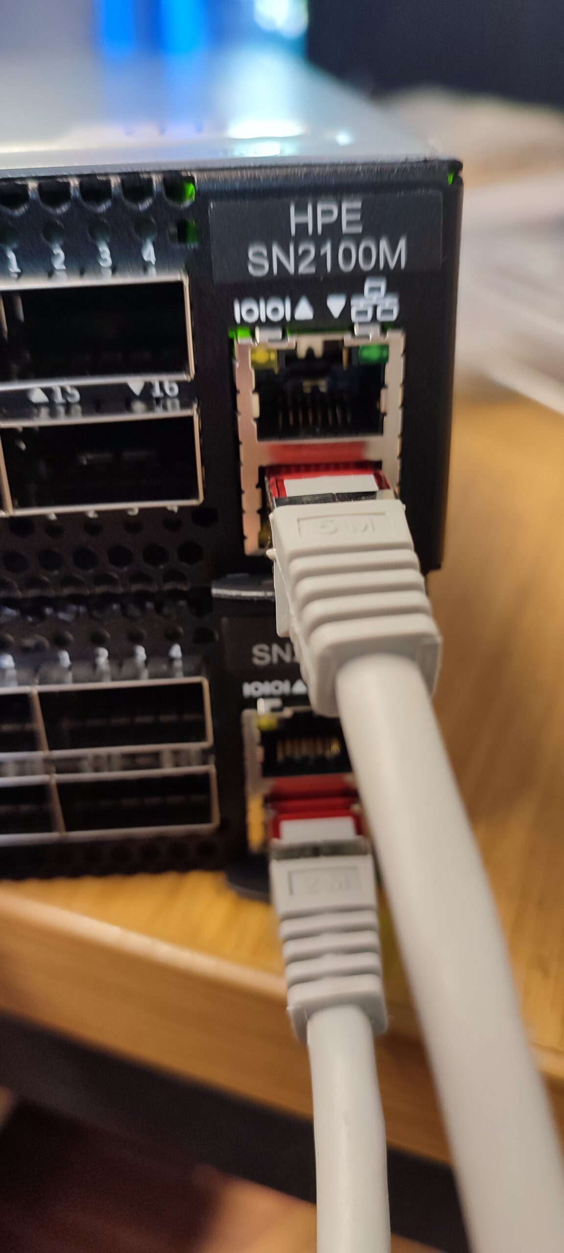
So, we finally received 2x HPE SN2100M switches for internal use. They will be our new switches for the 3x ProLiant DL325 Gen10 Plus v2 we recently got for our VMWare ESXi Cluster. The switches are “slightly” overkill for what we need, but they are what I got. soooo.
The initial plan was to get 10GbE switches, something like the Aruba 6300M Switch 24p SFP+ (JL658A), but for whatever reason, it kept escalating to these. I am not going to complain.
Anyway.
Here is a topology of what I am going to build in our shop, though it’s not really relevant to this post. I just like topologies. 🙂
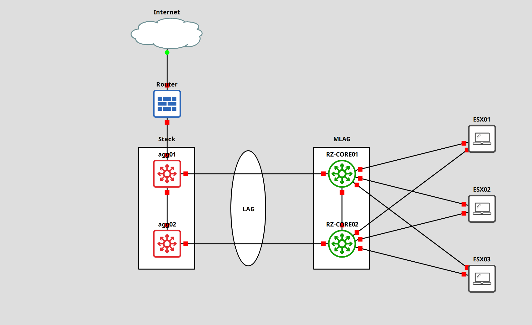
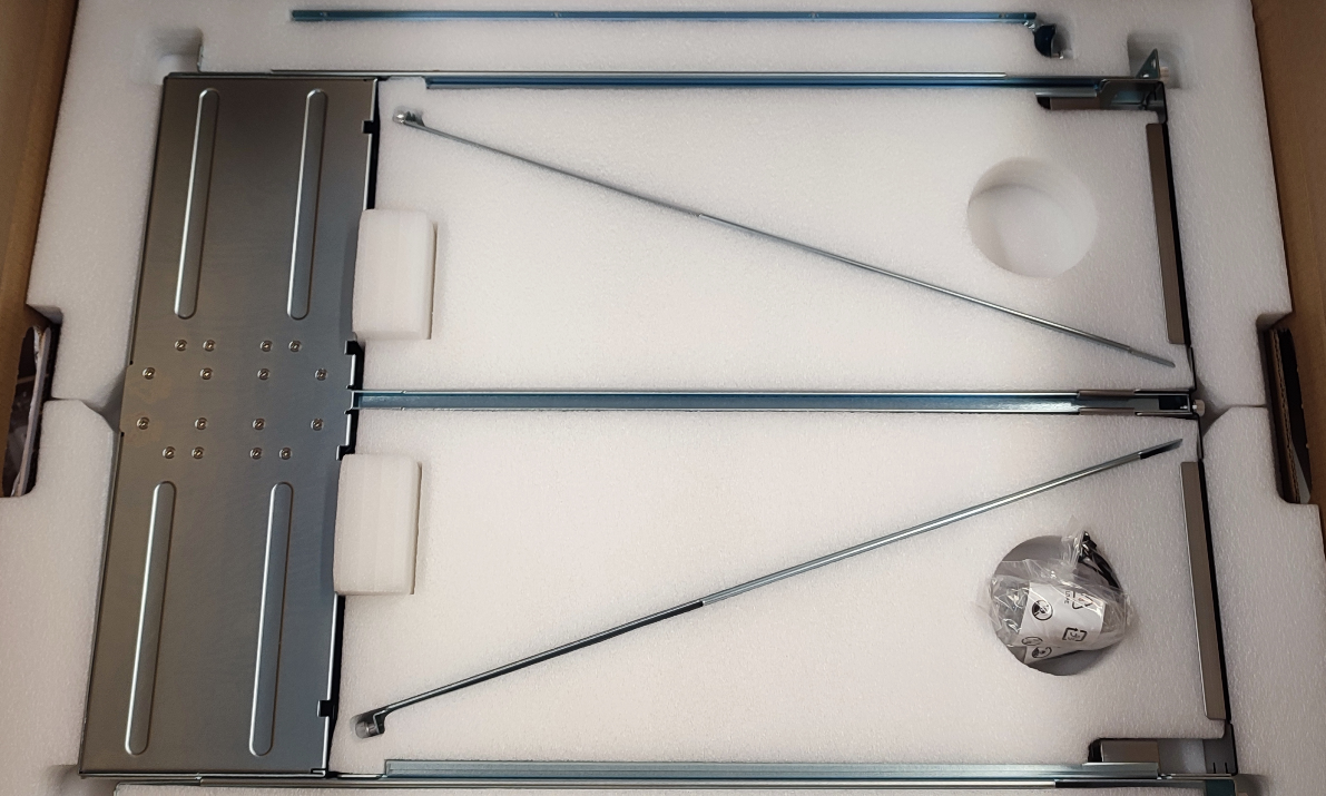
These are 16x100GbE QSFP28 Switches (you will need a license to enable 8 of the ports) that support speeds of 1, 10, 25, 40, 50, and 100GbE. The switches only have half the width, which allows us to have a cluster/stack in 1U. There is a special rack mount kit for this.
Here is the rack mount kit.
We can split each of the 100GbE QSFP28 to 4x 25GbE SFP28 with one of the following DAC, which we will need for our servers. Those (luckily) have 25GbE ports.
If we only had 10GbE available on our servers, I think we could use a 40GbE QSFP+ to 4x 10GbE SFP+ DAC.
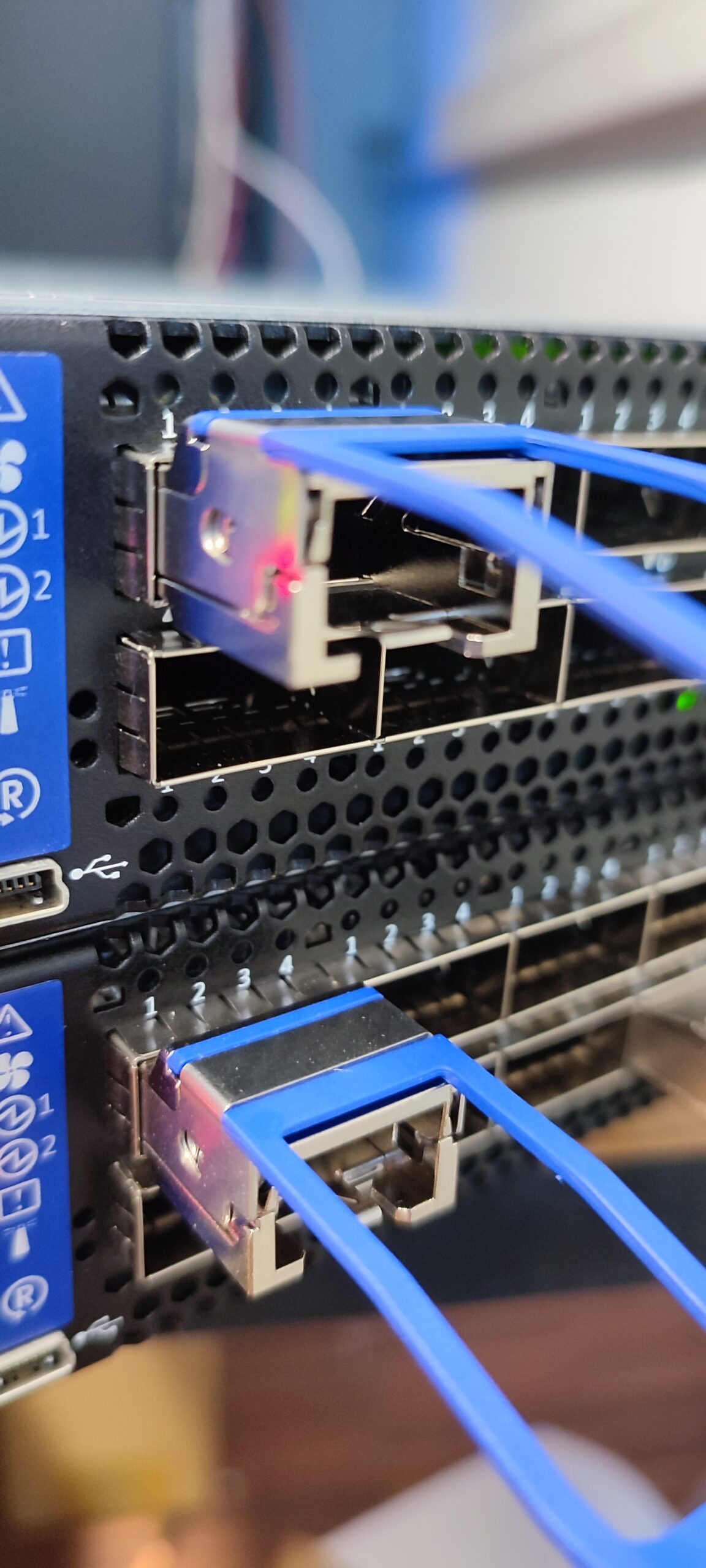
To connect the switches to each other, I will use a single (don’t ask why) 100GbE DAC. This will be for the MLAG IPL.
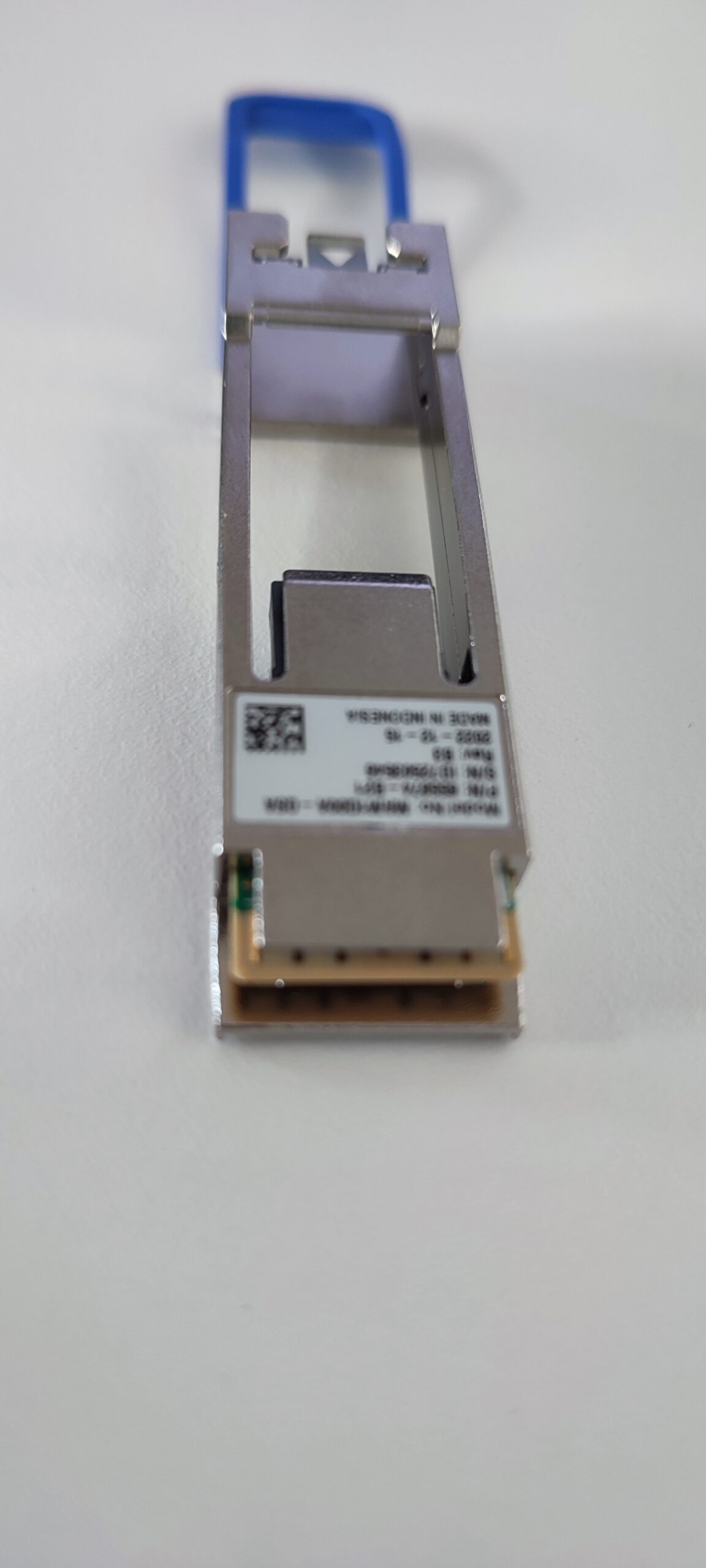
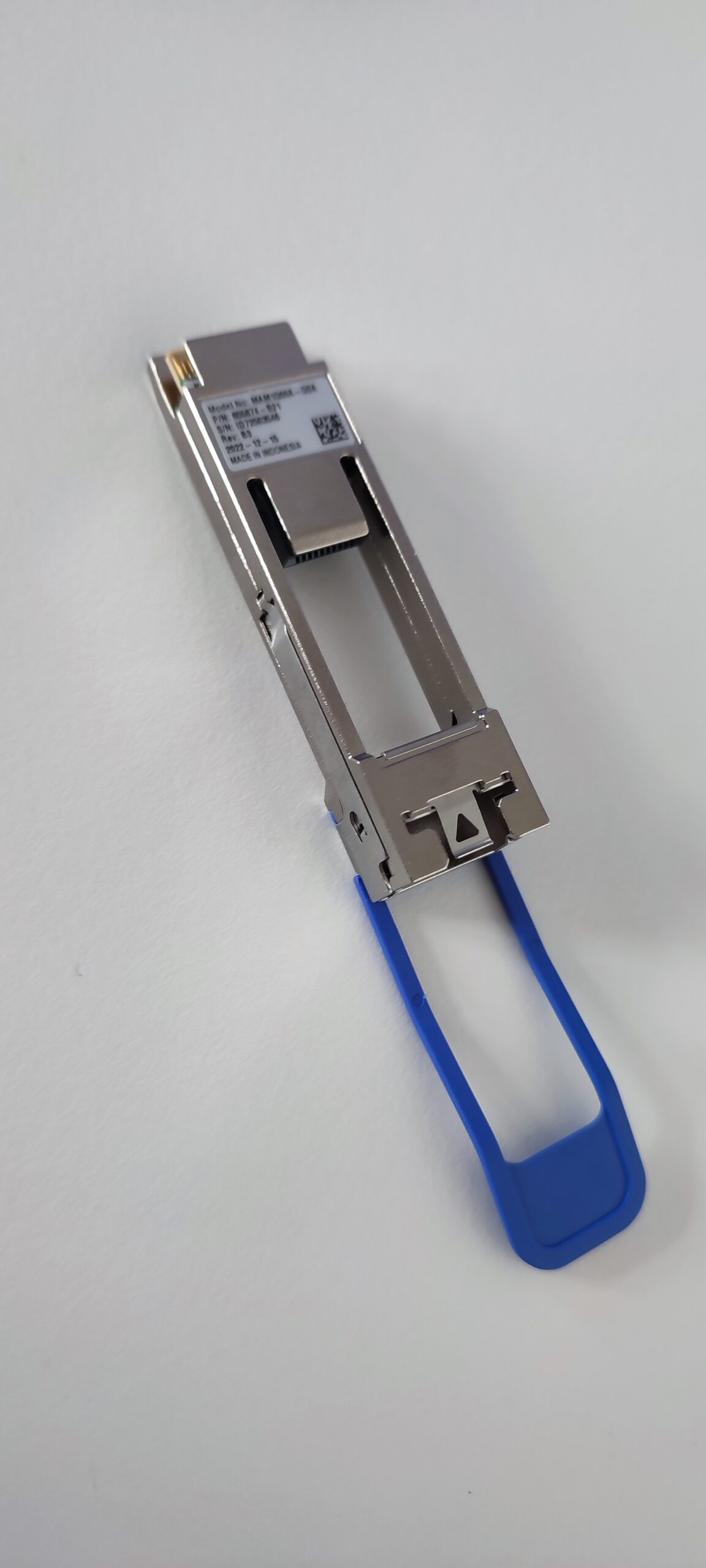
For the connection to our existing switches, we will use a QFSP to SFP+ Adapter, since our Switches, 3x Netgear M4300-52G-PoE+, only support up to 10GbE. Never tried one of these before, so it will be interesting to see if it works.
We plug these into the switch and an SFP+ module into the adapter.

One of the neat features this switch has, is the option to run docker images and virtual machines, though I couldn’t figure out how to get it running. Not very likely that we will have a use case for it, but I might create another post if I figure it out.
Also, there is support for a few popular automation tools like Ansible, SaltStack, and Puppet. You can get a list of Ansible modules from this page and a short guide here.
So, what’s the plan? First I need to figure out how to connect to these switches, then we will do the base configuration, set up MLAG, and create a port-channel / LAG spanning both switches, for the uplink to our switches. Lastly, we will figure out, how to set up the switch for the 4x SFP28 DAC.
Let’s start with the connection to the switches.
Setting up the Switch
Connecting to the Switch
I will use a serial cable for the initial connection. We have an RJ45 and Micro-USB port. The baud rate is 115200.
To actually connect, I will use “screen” which is a Linux tool, you can use Putty/Kitty on Windows.
Once in, we have to get through the initial setup. Unfortunately, I don’t have the steps anymore, forgot to take screenshots, but it should be self-explanatory. Set a password, and so on.
The default login is “admin/admin”.
Base setup
Ok, let’s begin. First let’s set the hostname, an IP address, the default gateway for the mgmt0 interface, the DNS server, and the search domain.
## Switch 1
# Switch into the enable and configuration mode.
switch >  enable
switch #  configure terminal

# Set the hostname
switch (config) #  hostname RZ-CORE01

# Switch into the mgmt0 interface and set the IP
RZ-CORE01 (config) #  interface mgmt0
RZ-CORE01 (config interface mgmt0) #  ip address 172.16.0.230 255.255.0.0
RZ-CORE01 (config interface mgmt0) #  exit

# Set the default gateway for the mgmt interface
RZ-CORE01 (config) #  ip route vrf mgmt 0.0.0.0/0 172.16.0.254

# Set the DNS server
RZ-CORE01 (config) #  ip name-server vrf mgmt 172.16.0.130

# Set the search domain
RZ-CORE01 (config) #  ip domain-list example.local
Do the same for the second switch.
## Switch 2
# Switch into the enable and configuration mode.
switch >  enable
switch #  configure terminal

# Set the hostname
switch (config) #  hostname RZ-CORE02

# Switch into the mgmt0 interface and set the IP
RZ-CORE02 (config) #  interface mgmt0
RZ-CORE02 (config interface mgmt0) #  ip address 172.16.0.231 255.255.0.0
RZ-CORE02 (config interface mgmt0) #  exit

# Set the default gateway for the mgmt interface
RZ-CORE02 (config) #  ip route vrf mgmt 0.0.0.0/0 172.16.0.254

# Set the DNS server
RZ-CORE02 (config) #  ip name-server vrf mgmt 172.16.0.130

# Set the search domain
RZ-CORE02 (config) #  ip domain-list example.local
Great. Let’s check it.
# Check the interface IP
RZ-CORE01 (config) #  show interfaces mgmt0 brief
Interface mgmt0 status:
  Comment          :
  VRF              : mgmt
  Admin up         : yes
  Link up          : yes
  DHCP running     : no (Static IP is configured)
  IP address       : 172.16.0.230
  Netmask          : 255.255.0.0
  IPv6 enabled     : no
  Speed            : 1000Mb/s (auto)
  Duplex           : full (auto)
  Interface type   : ethernet
  Interface source : bridge
  Bonding master   : vrf_mgmt
  MTU              : 1500
  HW address       : 00:00:00:00:00:00
Next, the route and the name server entries.
# Check the route on VRF mgmt
RZ-CORE01 (config) #  show ip route vrf mgmt
VRF Name mgmt:
  ------------------------------------------------------------------------------------------------------
  Destination       Mask              Flag     Gateway           Interface        Source     AD/M
  ------------------------------------------------------------------------------------------------------
  default           0.0.0.0                    172.16.0.254      mgmt0            static     1/1
  172.16.0.0        255.255.0.0                0.0.0.0           mgmt0            direct     0/0
# Check name servers
RZ-CORE01 (config) #  show hosts

Hostname        : RZ-CORE01
Name servers VRF: mgmt

Name servers:
      172.16.0.130                          configured
      172.16.0.132                          configured

Domain names:
      example.local                         configured

Static IPv4 host mappings:
  127.0.0.1                            --> localhost

Static IPv6 host mappings:
  ::1                                  --> localhost6

Automatically map hostname to loopback address     : yes
Automatically map hostname to IPv6 loopback address: no
Now we can patch the management interface and connect to the devices via SSH.
fedora-kde :: ~ » ssh admin@172.16.0.230
Set NTP
I also want to set NTP, to make sure the logs have the correct timestamp.
## Switch 1
# Set NTP Server
RZ-CORE01 (config) #  ntp server 0.de.pool.ntp.org
RZ-CORE01 (config) #  ntp server 1.de.pool.ntp.org
Let’s check the configuration.
# Check NTP server settings
RZ-CORE01 (config) #  show ntp
NTP is administratively            : enabled
VRF name                           : mgmt
NTP Authentication administratively: disabled
NTP server role                    : enabled

Clock is synchronized:
  Reference: 144.76.59.106
  Offset   : -0.701 ms

Active servers and peers:
  144.76.59.106:
    Configured as      : 0.de.pool.ntp.org
    Conf Type          : serv
    Status             : sys.peer(*)
    Stratum            : 2
    Offset(msec)       : -0.701
    Ref clock          : 131.188.3.223
    Poll Interval (sec): 64
    Last Response (sec): 50
    Auth state         : none

  162.159.200.1:
    Configured as      : 1.de.pool.ntp.org
    Conf Type          : serv
    Status             : candidat(+)
    Stratum            : 3
    Offset(msec)       : -0.734
    Ref clock          : 10.214.8.6
    Poll Interval (sec): 64
    Last Response (sec): 50
    Auth state         : none
Create VLANs
Next, we need a few VLANs. Internally we mainly use them for customers (internal deployments), test environments, and IoT stuff, but we also need one for the MLAG inter-peer link (IPL). This will be used only on these switches.
For the IPL VLAN, I will use the ID 4000, since it’s the one from the documentation, and we do not use it internally, but you can choose whatever you want.
## Switch 1
# Create VLANs
RZ-CORE01 (config) #  vlan 4000
RZ-CORE01 (config vlan 4000) #  name MLAG-IPL
RZ-CORE01 (config vlan 4000) #  exit
RZ-CORE01 (config) #  vlan 5
RZ-CORE01 (config vlan 5) #  name Technik
RZ-CORE01 (config vlan 5) #  exit
Do the same on the second switch.
## Switch 2
# Create VLANs
RZ-CORE02 (config) #  vlan 4000
RZ-CORE02 (config vlan 4000) #  name MLAG-IPL
RZ-CORE02 (config vlan 4000) #  exit
RZ-CORE02 (config) #  vlan 5
RZ-CORE02 (config vlan 5) #  name Technik
RZ-CORE02 (config vlan 5) #  exit
Again, let’s check.
RZ-CORE01 (config) #  show vlan
------------------------------------------------------------------------------
VLAN      Name                      Ports
------------------------------------------------------------------------------

1         default                   Eth1/1,Eth1/2,Eth1/3,Eth1/4,Eth1/5,Eth1/6,
                                    Eth1/7,Eth1/9,Eth1/10,Eth1/11,Eth1/12,
                                    Eth1/13,Eth1/14,Eth1/15,Eth1/16
5         Technik
4000      MLAG-IPL
Setting up MLAG
Ok. Now we can begin with the MLAG setup. I will stay very close to the NVIDIA documentation. For the port-channel ID, I will be using 128, to avoid accidental changes on this port-channel and to make clear that this one is special.
The interface I will be using is the last available (1/8 since we did not license the rest). I tend to use the last ports for uplinks.
## Both Switches
# Enable IP routing
RZ-CORE01 (config) #  ip routing

# Enable LACP
RZ-CORE01 (config) #  lacp

# Enable QoS to avoid congestion on the IPL
RZ-CORE01 (config) #  dcb priority-flow-control enable force

# Enable the MLAG protocol
RZ-CORE01 (config) #  protocol mlag

## Setup the IPL
# Configure port-channel
RZ-CORE01 (config) #  interface port-channel 128
RZ-CORE01 (config interface port-channel 128) #  exit

# Map a port to the port-channel
RZ-CORE01 (config) #  interface ethernet 1/8 channel-group 128 mode active

# Activate IPL on this port-channel
RZ-CORE01 (config) #  interface port-channel 128
RZ-CORE01 (config interface port-channel 128) #  ipl 1

# Enable QoS on this interface
RZ-CORE01 (config interface port-channel 128) #  dcb priority-flow-control mode on force
RZ-CORE01 (config interface port-channel 128) #  exit

# Create a VLAN interface and set MTU to 9216
RZ-CORE01 (config) #  interface vlan 4000
RZ-CORE01 (config interface vlan 4000) #  mtu 9216
From here on, the configuration is slightly different on each switch.
## Switch 1
# Set an IP address for the IPL link
RZ-CORE01 (config interface vlan 4000) #  ip address 192.168.255.1 /30

# Map the VLAN interface to be used on the IPL. Also set the peer IP address, this is the IP of the second switch.
RZ-CORE01 (config interface vlan 4000) #  ipl 1 peer-address 192.168.255.2
## Switch 2
# Set an IP address for the IPL link
RZ-CORE02 (config interface vlan 4000) #  ip address 192.168.255.2 /30

# Map the VLAN interface to be used on the IPL. Also set the peer IP address, this is the IP of the primary switch.
RZ-CORE02 (config interface vlan 4000) #  ipl 1 peer-address 192.168.255.1
Now we set a virtual IP (VIP) and virtual system MAC for the MLAG. This is optional but recommended. We should also use an IP address from the mgmt0 subnet.
## Switch 1
# Create the VIP
RZ-CORE01 (config) #  mlag-vip my-vip ip 172.16.0.229 /16

# Create the virtual MAC
RZ-CORE01 (config) #  mlag system-mac 0e:00:00:00:00:01
## Switch 2
# Create the VIP
RZ-CORE02 (config) #  mlag-vip my-vip

# Create the virtual MAC
RZ-CORE02 (config) #  mlag system-mac 0e:00:00:00:00:01
For the last step, we need to enable MLAG.
## Switch 1
# Enable MLAG
RZ-CORE01 [my-vip: master] (config) #  mlag
RZ-CORE01 [my-vip: master] (config mlag) #  no shutdown
## Switch 2
# Enable MLAG
RZ-CORE02 [my-vip: standby] (config) #  mlag
RZ-CORE02 [my-vip: standby] (config mlag) #  no shutdown
We are done with the MLAG setup. Let’s check if everything is up and running.
RZ-CORE01 [my-vip: master] (config) #  show mlag
Admin status: Enabled
Operational status: Up
Reload-delay: 30 sec
Keepalive-interval: 1 sec
Upgrade-timeout: 60 min
System-mac: 0e:00:00:00:00:01

MLAG Ports Configuration Summary:
 Configured: 0
 Disabled:   0
 Enabled:    0

MLAG Ports Status Summary:
 Inactive:       0
 Active-partial: 0
 Active-full:    0

MLAG IPLs Summary:
------------------------------------------------------------------------------------------------------------------
ID   Group         Vlan       Operational  Local                                    Peer                                     Up Time              Toggle Counter
     Port-Channel  Interface  State        IP address                               IP address
------------------------------------------------------------------------------------------------------------------
1    Po128         4000       Up           192.168.255.1                             192.168.255.2                             0 days, 00:17:35     7

MLAG Members Summary:
---------------------------------------------------------------------
System-id           State                        Hostname
---------------------------------------------------------------------
00:00:00:00:00:00   Up                           <RZ-CORE01>
00:00:00:00:00:00   Up                            RZ-CORE02
Seems up and operational.
Creating an MLAG interface
At this point, we can create a LAG interface that spans over both switches. I will also set the switchport mode (VLAN tagging). Since we need to use the QSFP28 to SFP+ adapters, we also need to adjust the port speed on the interface before mapping it to the port-channel.
## Switch 1
# Create an MLAG interface
RZ-CORE01 [my-vip: master] (config) #  interface mlag-port-channel 1
RZ-CORE01 [my-vip: master] (config interface mlag-port-channel 1) #  exit

# Bind an port to the MLAG interface
RZ-CORE01 [my-vip: master] (config) #  interface ethernet 1/6
RZ-CORE01 [my-vip: master] (config interface ethernet 1/6) #  shutdown
RZ-CORE01 [my-vip: master] (config interface ethernet 1/6) #  speed 10G
RZ-CORE01 [my-vip: master] (config interface ethernet 1/6) #  mlag-channel-group 1 mode active  # enables LACP in active mode
RZ-CORE01 [my-vip: master] (config interface ethernet 1/6) #  no shutdown
RZ-CORE01 [my-vip: master] (config interface ethernet 1/6) #  exit

# Enable the MLAG interface
RZ-CORE01 [my-vip: master] (config) #  interface mlag-port-channel 1
RZ-CORE01 [my-vip: master] (config interface mlag-port-channel 1) #  no shutdown

# Set switchport mode
RZ-CORE01 [my-vip: master] (config interface mlag-port-channel 1) #  switchport mode hybrid
RZ-CORE01 [my-vip: master] (config interface mlag-port-channel 1) #  switchport hybrid allowed-vlan all
RZ-CORE01 [my-vip: master] (config interface mlag-port-channel 1) #  exit
Do the same for the second switch.
## Switch 2
# Create an MLAG interface
RZ-CORE02 [my-vip: standby] (config) #  interface mlag-port-channel 1
RZ-CORE02 [my-vip: standby] (config interface mlag-port-channel 1) #  exit

# Bind an port to the MLAG interface
RZ-CORE02 [my-vip: standby] (config) #  interface ethernet 1/6
RZ-CORE02 [my-vip: standby] (config interface ethernet 1/6) #  shutdown
RZ-CORE02 [my-vip: standby] (config interface ethernet 1/6) #  speed 10G
RZ-CORE02 [my-vip: standby] (config interface ethernet 1/6) #  mlag-channel-group 1 mode active # enables LACP in active mode
RZ-CORE02 [my-vip: standby] (config interface ethernet 1/6) #  exit

# Enable the MLAG interface
RZ-CORE02 [my-vip: standby] (config) #  interface mlag-port-channel 1
RZ-CORE02 [my-vip: standby] (config interface mlag-port-channel 1) #  no shutdown

# Set switchport mode
RZ-CORE02 [my-vip: standby] (config interface mlag-port-channel 1) #  switchport mode hybrid
RZ-CORE02 [my-vip: standby] (config interface mlag-port-channel 1) #  switchport hybrid allowed-vlan all
RZ-CORE02 [my-vip: standby] (config interface mlag-port-channel 1) #  exit
Let’s check the interfaces.
RZ-CORE01 [my-vip: master] (config) #  show interfaces status
---------------------------------------------------------------------------------------------------------------
Port                  Operational state     Admin                           Speed             MTU               Description
---------------------------------------------------------------------------------------------------------------
mgmt0                 Up                    Enabled                         1000Mb/s (auto)   1500              -
Po128                 Up                    Enabled                                           9216              -
Mpo1                  Up                    Enabled                                           9216              -
Eth1/1                Down                  Enabled                         Unknown           9216              -
Eth1/2                Down                  Enabled                         Unknown           9216              -
Eth1/3                Down                  Enabled                         Unknown           9216              -
Eth1/4                Down                  Enabled                         Unknown           9216              -
Eth1/5                Down                  Enabled                         Unknown           9216              -
Eth1/6 (Mpo1)         up                    Enabled                         10G               9216              -
Eth1/7                Down                  Enabled                         Unknown           9216              -
Eth1/8 (Po128)        Up                    Enabled                         100G              9216              -
Eth1/9                Down                  Unlicensed                      Unknown           9216              -
Eth1/10               Down                  Unlicensed                      Unknown           9216              -
Eth1/11               Down                  Unlicensed                      Unknown           9216              -
Eth1/12               Down                  Unlicensed                      Unknown           9216              -
Eth1/13               Down                  Unlicensed                      Unknown           9216              -
Eth1/14               Down                  Unlicensed                      Unknown           9216              -
Eth1/15               Down                  Unlicensed                      Unknown           9216              -
Eth1/16               Down                  Unlicensed                      Unknown           9216              -
Changing Module-Type to Split mode for break-out cable
Next on the list are the break-out cables. We bought four of them, but for now, we will only use 2. To make the individual 25GbE ports available, we need to change the module type.
RZ-CORE01 [my-vip: master] (config) #  interface ethernet 1/1
RZ-CORE01 [my-vip: master] (config interface ethernet 1/1) #  shutdown
RZ-CORE01 [my-vip: master] (config interface ethernet 1/1) #  module-type qsfp-split-4
the following interfaces will be unmapped: 1/1
Type 'YES' to confirm split: YES
Once that’s done, the interface will look like this.
RZ-CORE01 [my-vip: master] (config) #  show interfaces status
----------------------------------------------------------------------------------------------------------------
Port                  Operational state     Admin                           Speed             MTU               Description
----------------------------------------------------------------------------------------------------------------
mgmt0                 Up                    Enabled                         1000Mb/s (auto)   1500              -
Po128                 Up                    Enabled                                           9216              -
Mpo1                  Up                    Enabled                                           9216              -
Eth1/1/1              Down                  Enabled                         Unknown           9216              -
Eth1/1/2              Down                  Enabled                         Unknown           9216              -
Eth1/1/3              Up                    Enabled                         25G               9216              -
Eth1/1/4              Down                  Enabled                         Unknown           9216              -
Eth1/2                Down                  Enabled                         Unknown           9216              -
Eth1/3                Down                  Enabled                         Unknown           9216              -
Eth1/4                Down                  Enabled                         Unknown           9216              -
Eth1/5                Down                  Enabled                         Unknown           9216              -
Eth1/6 (Mpo1)         Up                    Enabled                         10G               9216              -
Eth1/7                Down                  Enabled                         Unknown           9216              -
Eth1/8 (Po128)        Up                    Enabled                         100G              9216              -
Eth1/9                Down                  Unlicensed                      Unknown           9216              -
Eth1/10               Down                  Unlicensed                      Unknown           9216              -
Eth1/11               Down                  Unlicensed                      Unknown           9216              -
Eth1/12               Down                  Unlicensed                      Unknown           9216              -
Eth1/13               Down                  Unlicensed                      Unknown           9216              -
Eth1/14               Down                  Unlicensed                      Unknown           9216              -
Eth1/15               Down                  Unlicensed                      Unknown           9216              -
Eth1/16               Down                  Unlicensed                      Unknown           9216              -
And here is the result.
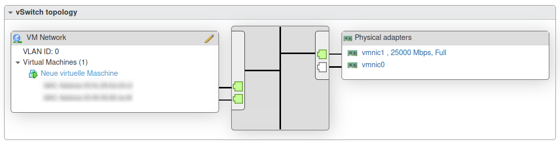
A nice 25Gbps link. This is the third host which isn’t in our productive cluster right now. The second interface will be patched later.
If you want to combine the port back into one, do the following.
RZ-CORE01 [my-vip: master] (config) #  interface ethernet 1/1/4
RZ-CORE01 [my-vip: master] (config interface ethernet 1/1/4) #  shutdown
RZ-CORE01 [my-vip: master] (config interface ethernet 1/1/4) #  exit
RZ-CORE01 [my-vip: master] (config) #  interface ethernet 1/1/3
RZ-CORE01 [my-vip: master] (config interface ethernet 1/1/3) #  shutdown
RZ-CORE01 [my-vip: master] (config interface ethernet 1/1/3) #  exit
RZ-CORE01 [my-vip: master] (config) #  interface ethernet 1/1/2
RZ-CORE01 [my-vip: master] (config interface ethernet 1/1/2) #  shutdown
RZ-CORE01 [my-vip: master] (config interface ethernet 1/1/2) #  exit
RZ-CORE01 [my-vip: master] (config) #  interface ethernet 1/1/1
RZ-CORE01 [my-vip: master] (config interface ethernet 1/1/1) #  shutdown
RZ-CORE01 [my-vip: master] (config interface ethernet 1/1/1) #  module-type qsfp
The following interfaces will be unmapped: 1/1/1 1/1/2 1/1/3 1/1/4.
Change the password and save the configuration
If you, like me, didn’t change the default password in the initial setup, this is how we can do it.
RZ-CORE01 [my-vip: master] (config) # username admin password 0 SECRET-PASSWORD
Also, do not forget to save the configuration on both switches.
RZ-CORE01 [my-vip: master] (config) # write memory
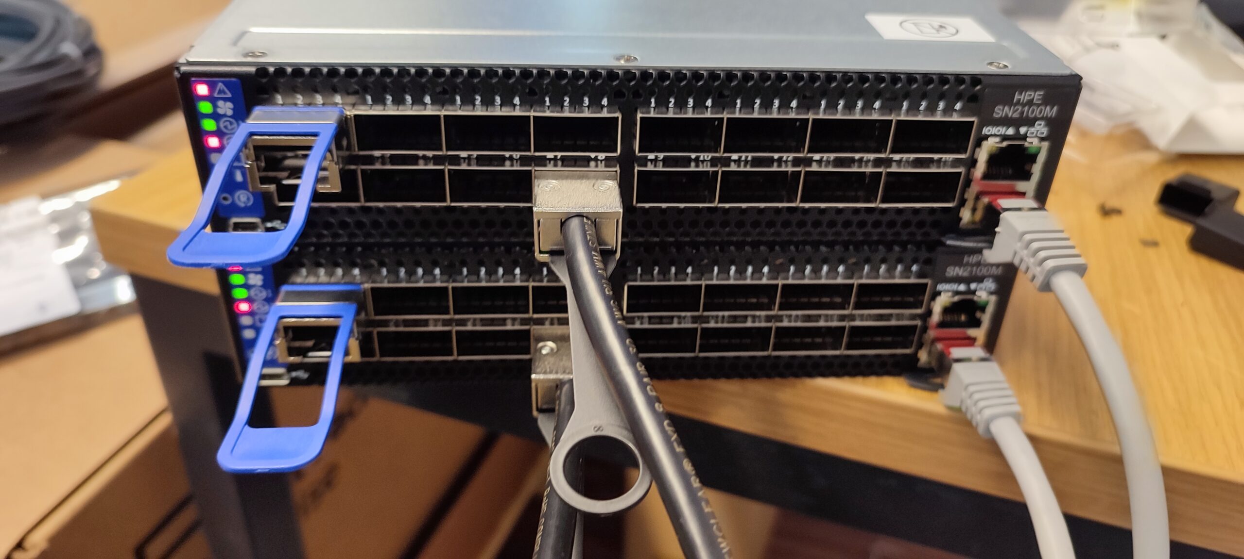
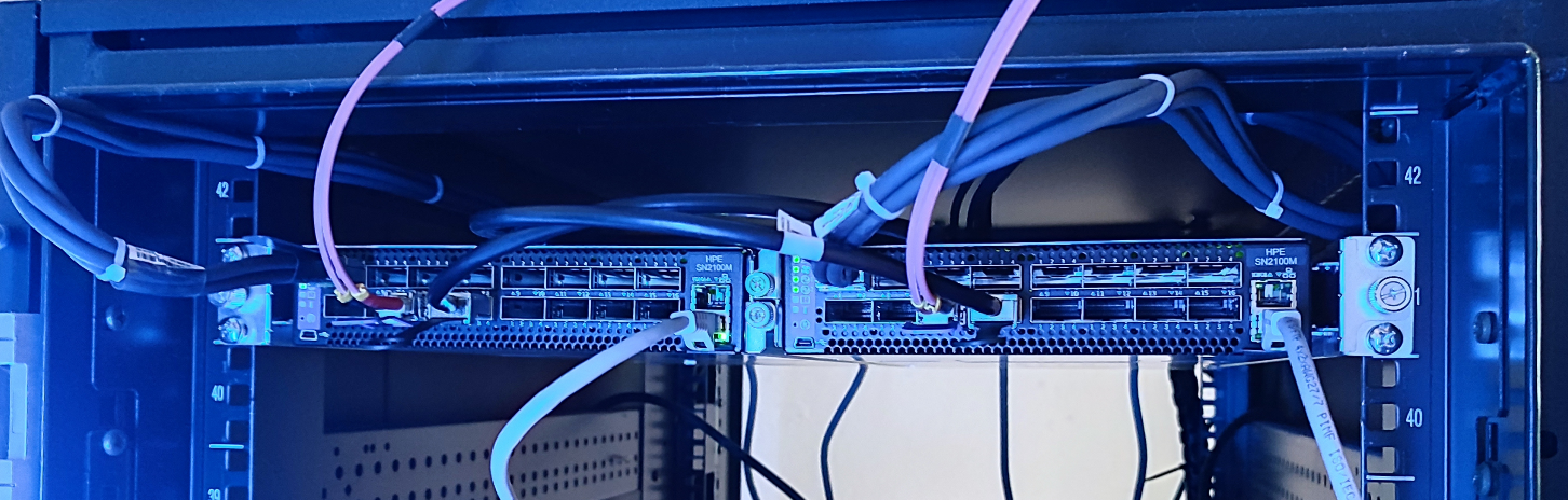
Done
Alright. That’s it. Here is the end result. The first port connects to the servers. The last (licensed) port 8 is used for the MLAG and the purple fiber optic cable is our uplink to our switches across the room. Port 7 is currently unused and will be used for redundancy if I ever get another 100GbE DAC.
The cabling isn’t great, but you have never seen the server room. 🙂 It’s actually horrendous.
At first, I wasn’t too happy with having another switch with a different OS in our network (I think we have 5 different manufacturers by now), but I do like these switches. The commands are easy enough to understand, to some extent, and the documentation is OK. I have seen better, but it’s serviceable.
By the way, I am aware that having 25GbE links to the ESX hosts is kind of pointless if the uplinks are 2x10GbE only. But even 10GbE is too much for us, we don’t generate that kind of large traffic. Mostly remote sessions and ERP connections. The only use case is for backups, testing purposes, and vMotion.
Well, that’s not entirely true. We did receive an HPE Alletra 6000 Series, if I remember correctly, which should be iSCSI. I’m probably not going to configure the storage, but it is very likely that I will handle the networking. Also, very much overkill.