Hello there.
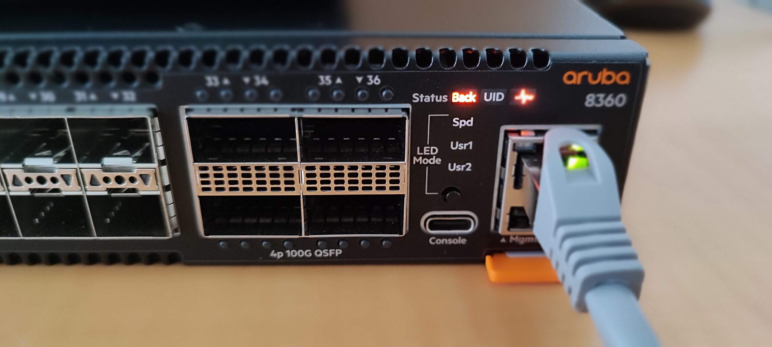
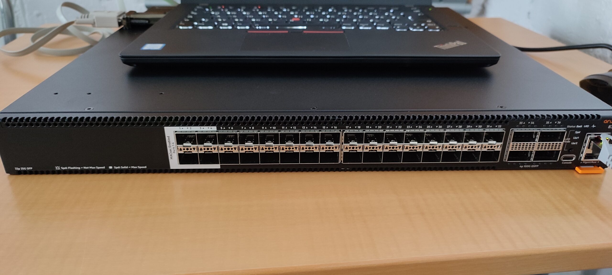
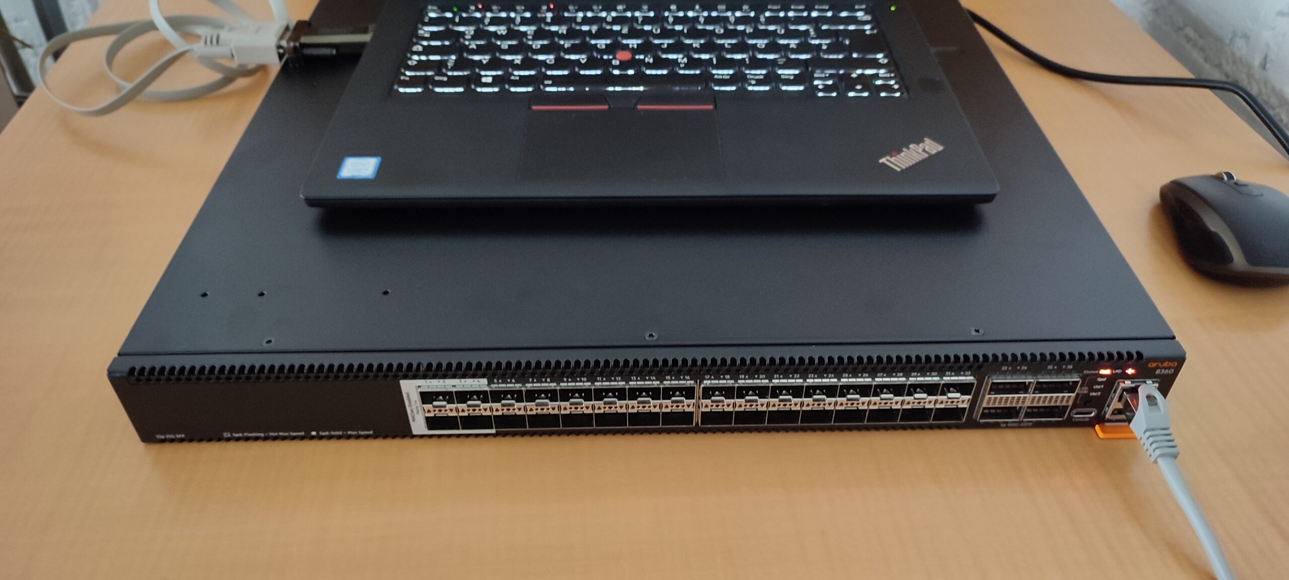
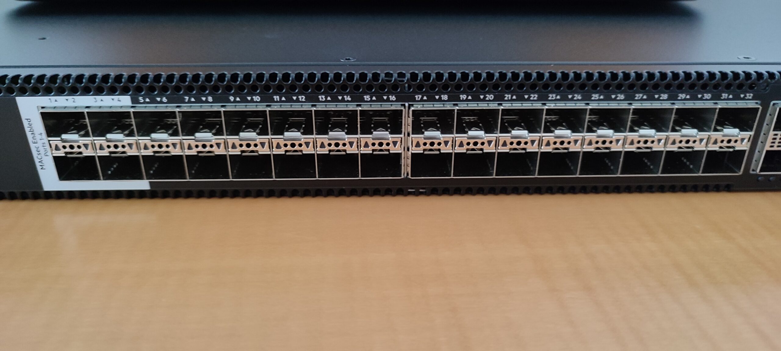
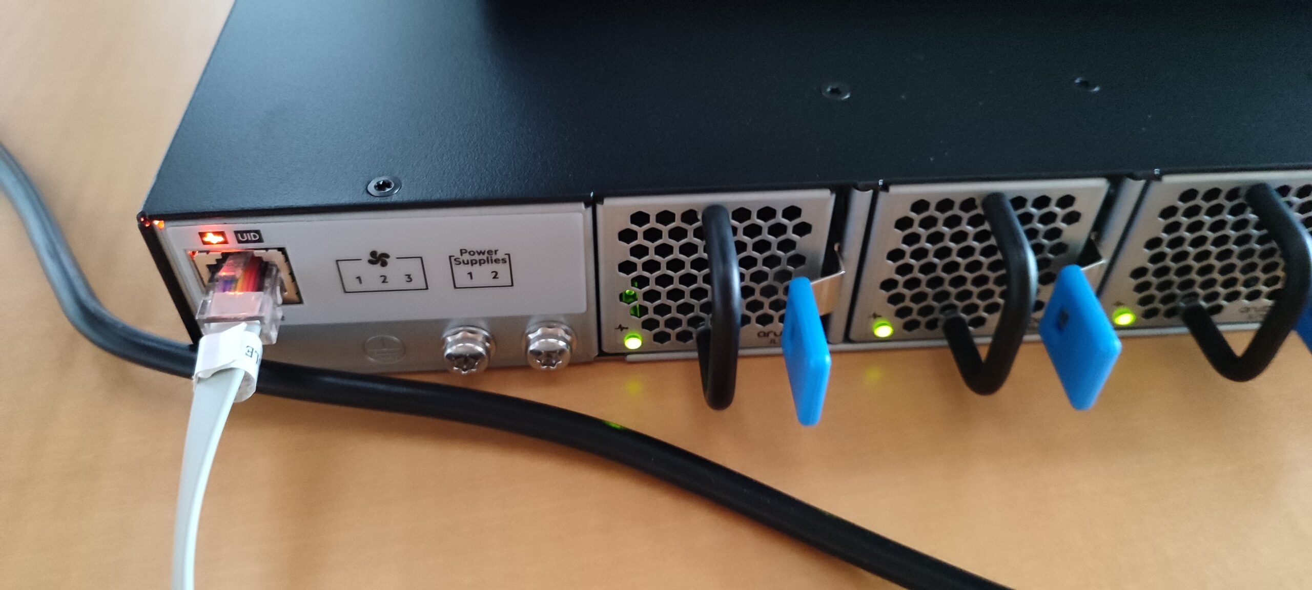
Today I want to go through the basic configuration of an Aruba 8360-32Y4C. Such a beautiful device. Look at it…
Aruba 8360-32Y4C. It has 32x 1GbE/10GbE/25GbE ports. 4 of those are with MACsec. On top of that, it comes with 4x 40GbE/100GbE ports. Up to 2,4TBit/s bidirectional switching and 1,145 Mpps for forwarding packages. Don’t know how true that is.
Where was I? Ah yes… Basic configuration.
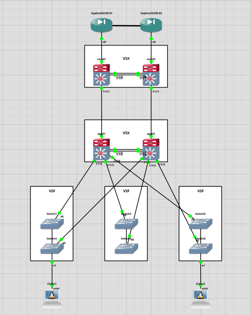
I currently have 4 of those in the office. These are planned for a new location. A customer wants to use it as their new HQ basically. 2 of the switches will be used as a core and the other two as aggregation switches (which wasn’t my idea). The core switches will be connected to 2 Sophos XG 330 in an active / passive configuration.
We will use 2 of the 100GbE ports for the VSX Cluster and the other two for the interconnect between the core and aggregation switches.
For the interconnect and VSX we will use “Aruba 100G QSFP28 MPO SR4 MMF Transceiver (JL309A)”. Honestly, I do not have any experience with MPO connectors. So we will see how this goes.
Also, I do not know, why they didn’t just order DAC cables for the VSX. Would make the whole thing a bit simpler.
For the access switches, they went with Aruba 2930F which we will stack via VSF. Might do a guide on those as well. We will connect them with 2x 10GbE fiber links in a LAG/LACP to the aggregation switches.
Here is a simple topology.
I will do most of the configuration via the serial port. We could use the MGMT port at the front of the device. This port should grab an IP address via DHCP. But the device is right next to me so… why bother?
Might connect the MGMT port later to our network, when it comes to configuring the VSX. But I will leave this for part 2.
So. Let’s begin.
First steps
We will start with simply powering the switches up and connecting the serial cable. As a USB to Serial Adapter, I am using the “Digitus USB2.0 Serial Adapter“. If you are using Windows 10/11 you can connect via the application “Putty”.
Once you start the application you have the option for serial. Enter the COM, the baud rate (115200 for Aruba) and click on connect.
Since I am running Fedora Linux I am going to use “screen”. You can install it through the package manager of your distribution. All of the popular ones should offer it.
fedora-kde :: ~ » sudo dnf install screen
Once that’s done, enter the “dmesg” command with the following option. Connect the Adapter to your laptop and find out which tty it attaches to. It should show up in the CLI.
fedora-kde :: ~ » dmesg -w
[ 9211.424841] usb 1-4: Detected FT232RL
[ 9211.425514] usb 1-4: FTDI USB Serial Device converter now attached to ttyUSB3
ttyUSB3 it is.
now connect the cable to your adapter and enter the “screen” command with the correct tty. ttyUSB3 in my case.
fedora-kde :: ~ » sudo screen /dev/ttyUSB3 115200
You should now see a login prompt. What you are seeing here is actually from the “ArubaOS-CX Simulator” since I already started the configuration and forgot to take a screenshot.
Enter the username “admin”. Leave the password empty and confirm. It will ask you to create a new password. You can hit “Enter” twice to leave the password blank. I will change this later.
switch login: admin
Password:


Please configure the 'admin' user account password.
Enter new password:
Confirm new password:
Basic configuration
Now we are in the “manager” context. Here you can, among other things, use a few network diagnostic tools and show system configurations. For instance “show system” will show you information like hostname, firmware and base mac address.
switch# show system
Hostname           : switch
System Description : Virtual.10.08.0001
System Contact     :
System Location    :

Vendor             : Aruba
Product Name       : ABC123 ArubaOS-CX_OVA
Chassis Serial Nbr : OVAFDE94B
Base MAC Address   : 080009-fde94b
ArubaOS-CX Version : Virtual.10.08.0001

Time Zone          : UTC

Up Time            : 9 minutes
CPU Util (%)       : 20
Memory Usage (%)   : 34
Let us switch to the “configuration” context.
switch# configure terminal
// You could also abbreviation the command like this.
switch# conf
// It would get the same result.
Now let’s do some of the basic configurations. I will start with the hostname.
// Set hostname
switch(config)# hostname core01
core01(config)#
Next, the Vlans, corresponding names, required IP address and the route to the default gateway. This is just an example and does not represent the customers configuration.
// Creating the vlans
core01(config)# vlan 10,20,30,40,50,60,70
core01(config-vlan-<10,20,30,40,50,70>)# exit
// Switch into the "vlan 10" context
core01(config)# vlan 10
// Name the vlan
core01(config-vlan-10)# name SERVER
core01(config-vlan-10)# vlan 20
core01(config-vlan-20)# name CLIENT
core01(config-vlan-20)# vlan 30
core01(config-vlan-30)# name MGMT
core01(config-vlan-30)# vlan 40
core01(config-vlan-40)# name VOIP
...
// Switch into the "vlan 30 interface" context.
core01(config-vlan-70)# interface vlan 30
// Assign IP to "vlan 30"
core01(config-if-vlan)# ip address 10.155.20.101/24
// Verify
core01(config-if-vlan)# show ip interface vlan30

Interface vlan30 is up
 Admin state is up
 State information:
 Hardware: Ethernet, MAC Address: 08:00:09:fd:e9:4b
 IP MTU 1500
 IPv4 address 10.155.20.101/24

core01(config-if-vlan)# exit
// Set the default route
core01(config)# ip route 0.0.0.0/0 10.155.20.254
Since we will use VLAN 30 as the management VLAN and not the designated MGMT port at the front of the device, we will have to configure ssh and the https-server to listen on the default VRF.
We could probably also assign “VLAN 30” to its own VRF to make it more secure. But this is fine for now.
// Configure SSH
core01(config)# ssh server vrf default
// Configure HTTPS Server
core01(config)# https-server vrf default
Now we are done, with what I would consider a basic setup.
Spanning-Tree Configuration
Next, we will configure STP. Yes, this is the core switch, but it probably won’t actually route anything. The routing will be done by the two Sophos XG 330. Don’t ask me why we have these then. Let’s call it “future proofing”.
This will be a very simple configuration. I am going to use the default protocol on these devices (MSTP) and just set the “config-name”, “config-revision” and “priority”. Setting the “config-name” and “config-revision” isn’t exactly required, since it should fallback to RSTP but it’s easy to configure and gives us flexibility in the future.
// Enable STP
core01(config)# spanning-tree
// Set config-name, config-revision and priority
core01(config)# spanning-tree config-name STP
core01(config)# spanning-tree config-revision 1
core01(config)# spanning-tree priority 2
// Check the configuration
core01(config)# show spanning-tree mst-config

MST configuration information
   MST config ID        : STP
   MST config revision  : 1
   MST config digest    : AC36177F50283CD4B83821D8AB26DE62
   Number of instances  : 0

Instance ID     Member VLANs
--------------- ----------------------------------
0               1-4094

core01(config)# show spanning-tree summary root

STP status                   : Enabled
Protocol                     : MSTP
System ID                    : 08:00:09:fd:e9:4b

Root bridge for STP Instance : 0

                                                Root Hello Max Fwd
Instance ID     Priority Root ID                cost  Time Age Dly    Root Port
--------------- -------- ----------------- --------- ----- --- --- ------------
0                   8192 08:00:09:fd:e9:4b         0     2  20  15            0
Set user password
Let me show you how to set the user password, as we left it blank earlier. I will not set mine since the customer will set the password himself, once the device is in production.
core01(config)# user admin password plaintext <SECRET PASSWORD>
Great. I guess I will end it here for this part. In the next one, we will build the VSX Cluster and configure LAG/LACP on the 100GbE ports for the ISL and uplink to the aggregation switches.
Until next time.
