Hello there. Today, I want to take a look at “NetEdit”. A “visual network editor” for the ArubaOS-CX switches, which can be used free of charge for up to 25 switches, if remember correctly. I never used it before, so everything you see in this post, I will have done for the first time myself.
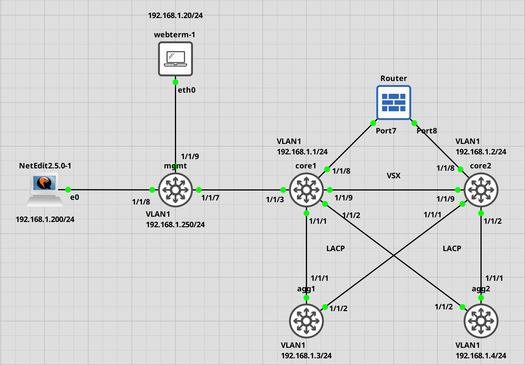
Anyway, I am going to use the latest version at the time of writing, which would be 2.5.0. To have something to test it with, I configured 5 switches. 2 will be in a VSX cluster, acting as the “core” switching, 2 will be my access switches, and one for the management. Additionally, to add to the fun, I set up a Sophos XGS firewall. Probably won’t see any use here, but who knows.
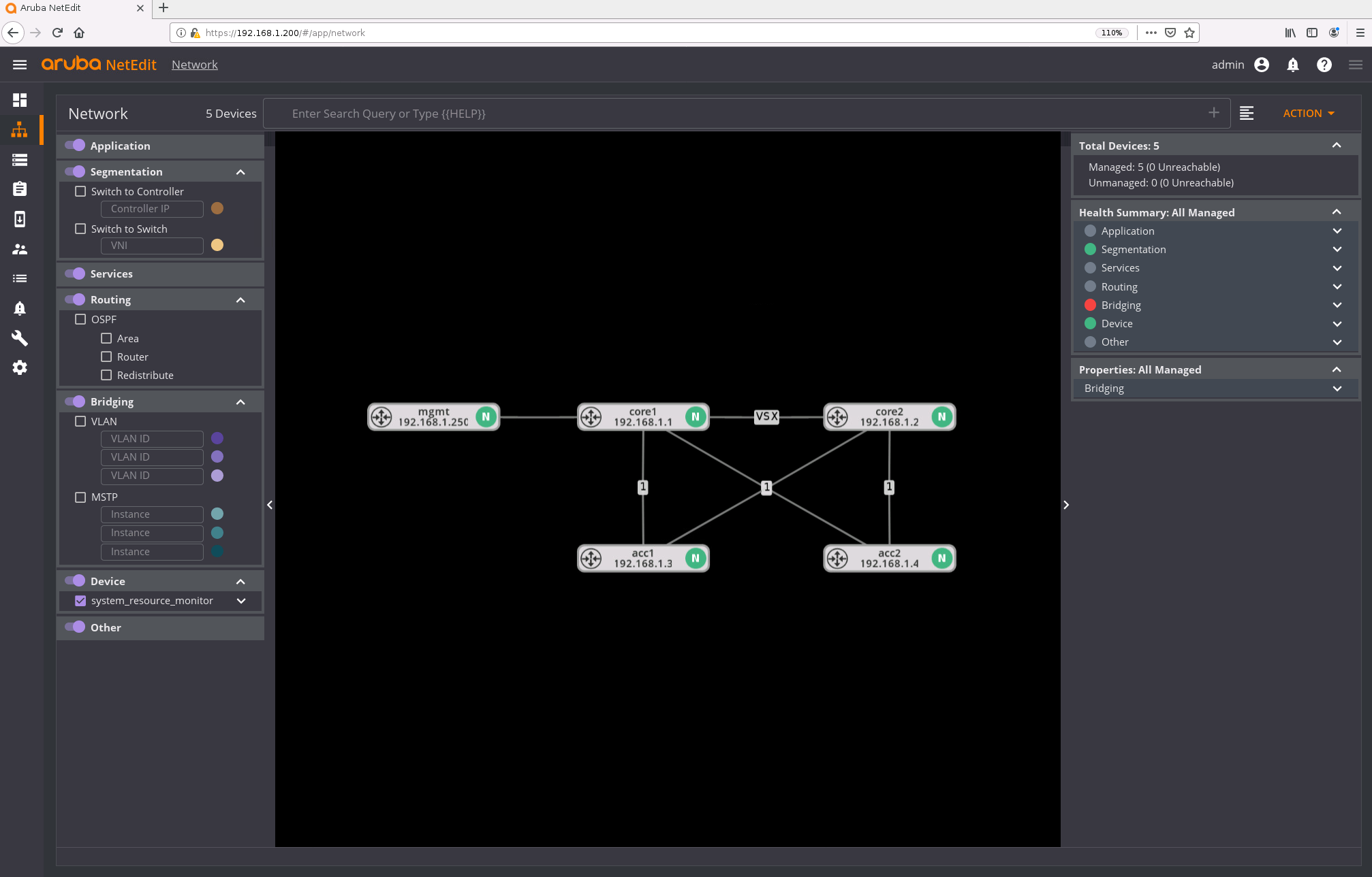
Here is the Topology.
Alright. Let’s start with importing the vmdk into GNS3.
GNS3 Appliance Import
Download the OVA from Aruba, and extract it until you have the vmdk file.
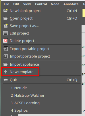
Next, open GNS3 and select “new template” from the “File” drop-down.
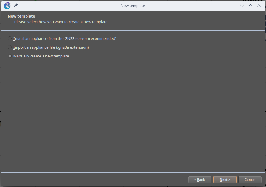
Select “Manually create a new template” and click on Next.
In the new window, select “Qemu VMs” and click on “new”.
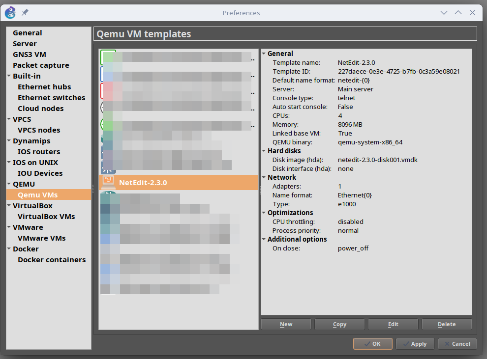
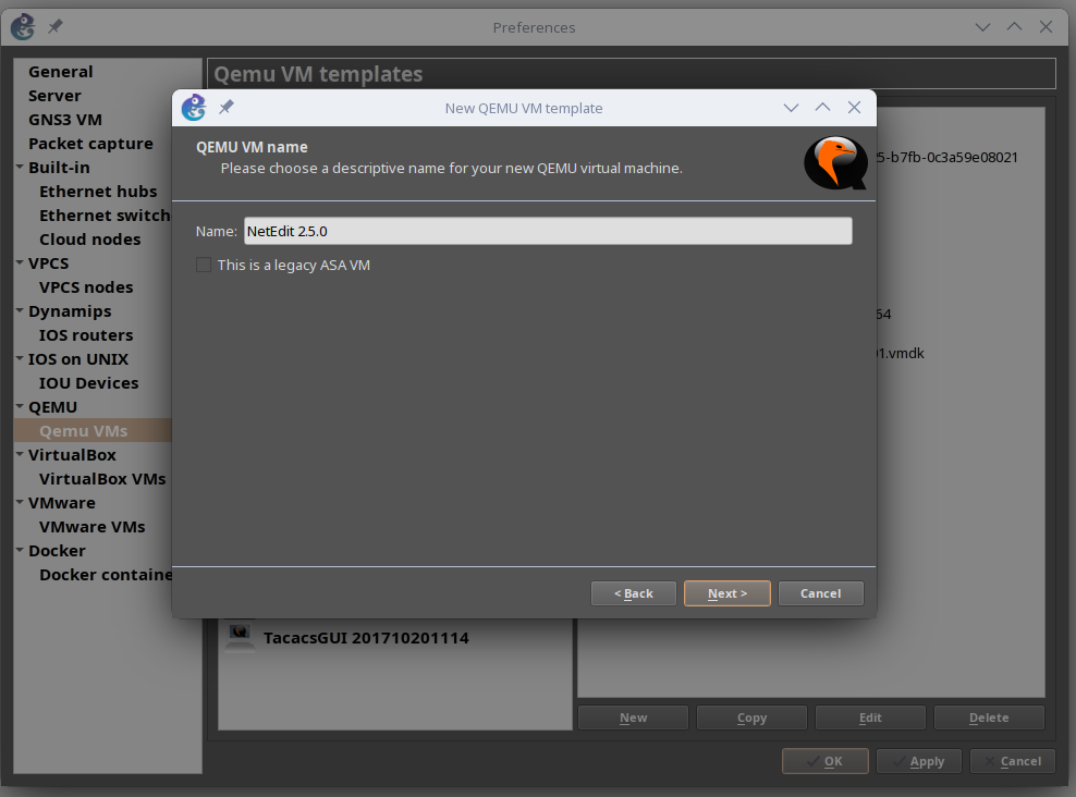
Choose a fitting name.
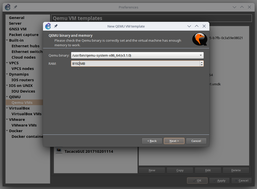
Here we can set the RAM, that should be assigned to the VM. I will set it to 8GB.
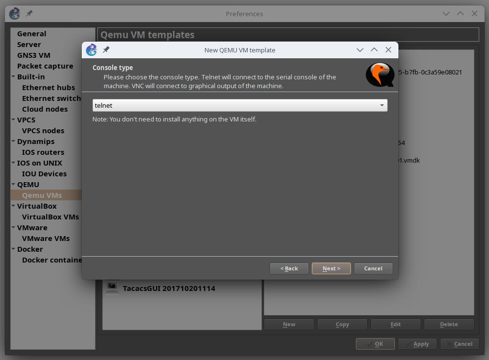
“Telnet” is fine. Click on Next.
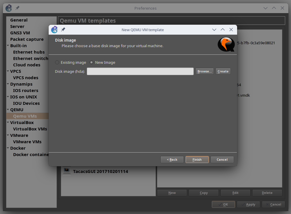
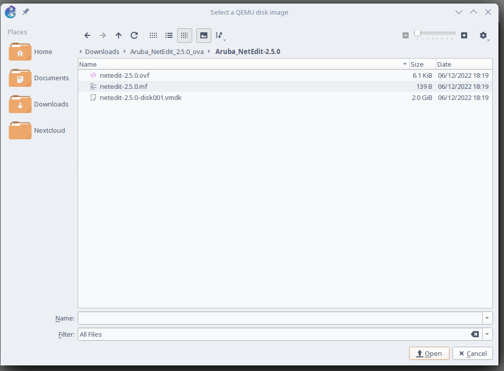
Select “New Image” and choose your newly extracted vmdk file.
After this, GNS3 will upload the file and create a new template.
NetEdit initial configuration
Start the NetEdit VM. Once it booted up, log in with “neadmin”. No password.
Debian GNU/Linux 10 netedit-server ttyS0

netedit-server login: neadmin
You will have to set your password immediately, so let’s do that.
You are required to change your password immediately (administrator enforced)
New password:
Retype new password:

Installing and configuring netedit-svr service
[sudo] password for neadmin:


 Netedit Service does not exist. Installing the Netedit Service ...
Once you type in your password, NetEdit will start the service configuration. But, if you are running this in GNS3 like me, then you will run into an issue. The screen size of the terminal session is too small, by apparently one pixel.
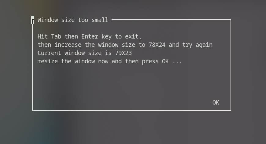
Confirm the window 3 times, and you will land back on the terminal. First, we have to take care of the screen size. To adjust the current size, type in the following.
neadmin@netedit-server:~$ stty cols 130 rows 130
Next, start the netedit configuration script again.
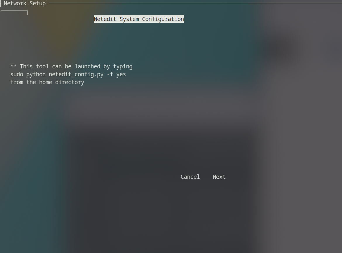
neadmin@netedit-server:~$ sudo python netedit_config.py -f yes
And we will be back into the setup. Let’s continue.
Select “Next” with the TAB button and confirm.
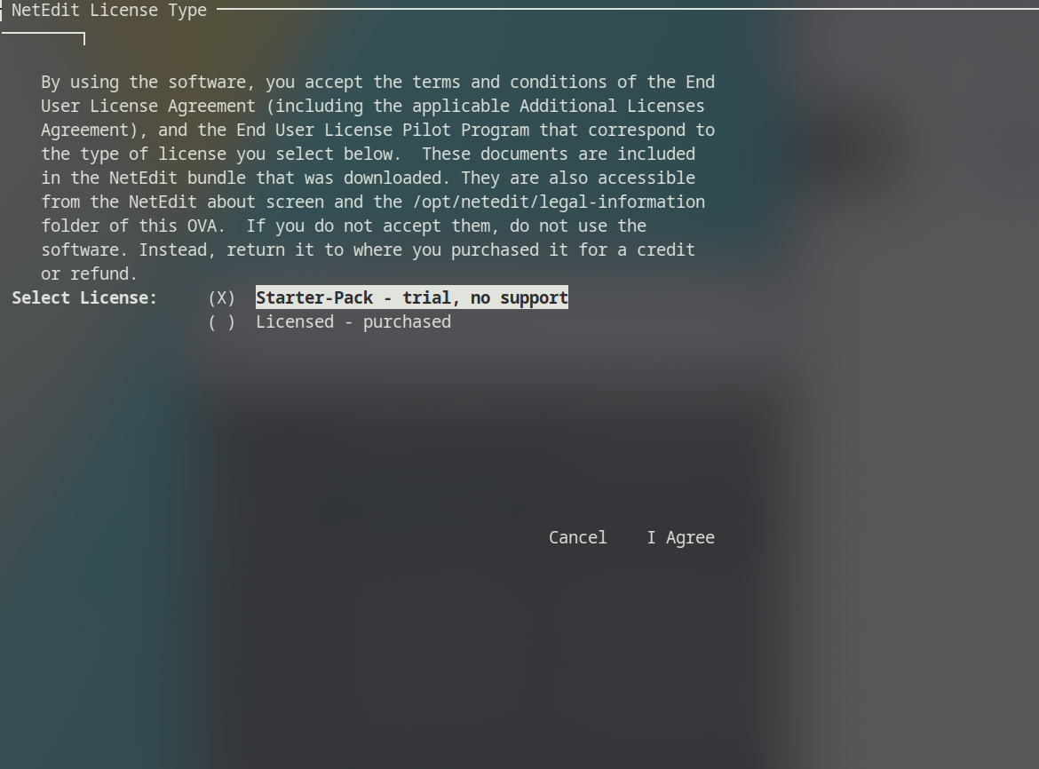
Accept the “Starter Pack”.
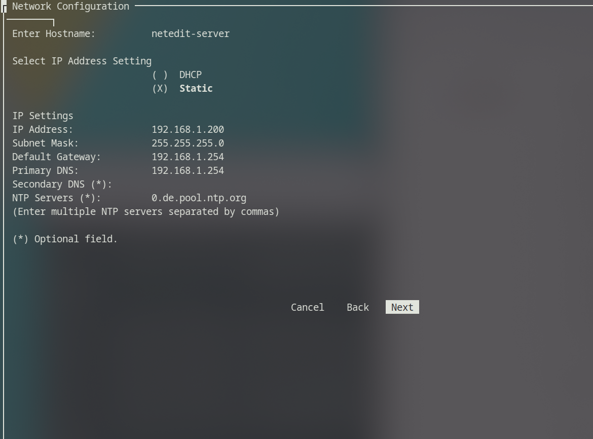
If you want to use DHCP, you can leave the default configuration. I want a static IP, so selected “Static” and typed in the IP and network I want.
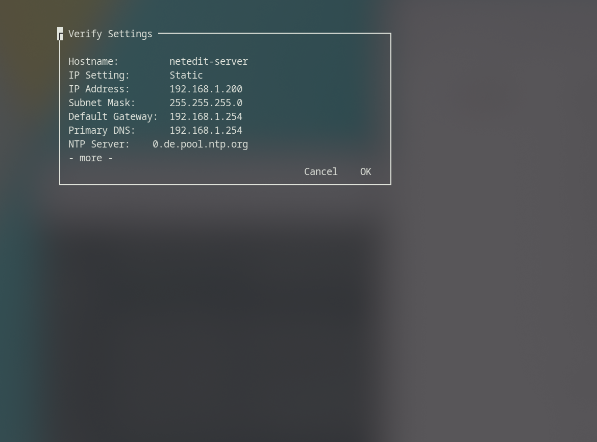
Check your settings and confirm.
Great. That’s it for the initial configuration. After a few minutes, we should be able to access the web interface. I will use a VM called “webterm” to access it. You can download it from the GNS3 website. I should have a post on this as well.
NetEdit Web interface
First Login
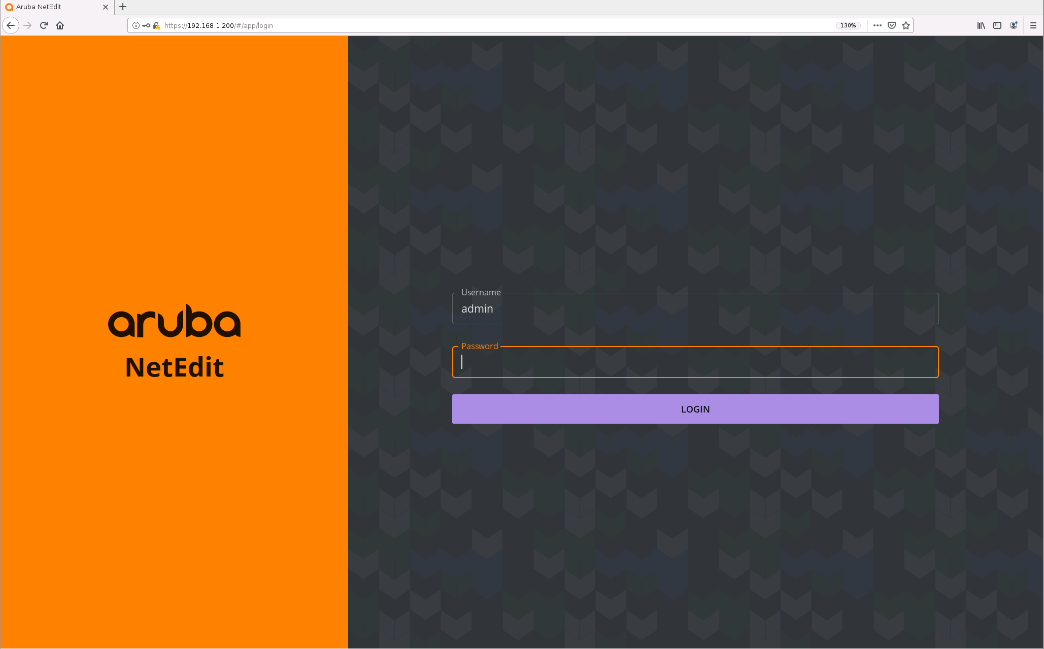
The login credentials are “admin” for the username. The password is empty.
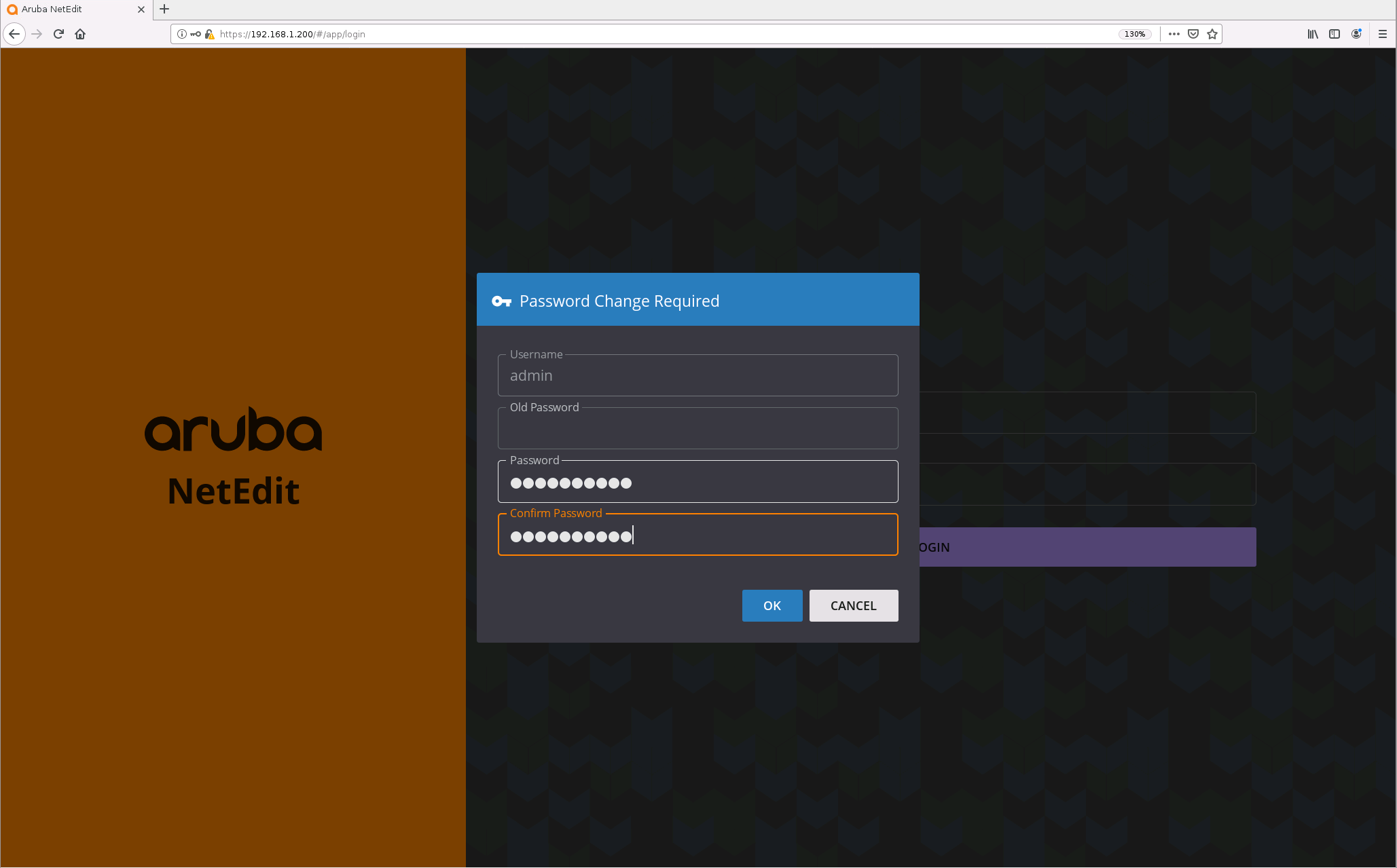
On our first login, we have to set a new password.
And, we are in.
Adding Switches
Now, to the main part. We want to add a few switches. If you are using the OOBM interface on the Aruba Switches, then you won’t have to do this next step, since the WebUI is already enabled. I will be using the “default” vrf, so I have to allow access to the web interface of the switches from that vrf. We have to do this for every switch.
core1(config)# https-server vrf default
Alright. Now let’s add the switches to NetEdit. First, we have to add the credentials. Navigate to the settings -> Device Credentials. Click on the “+” in the top right corner.
In case you haven’t created a password on the switches yet, here is how you add one.
core1(config)# user admin password plaintext PASSWORD
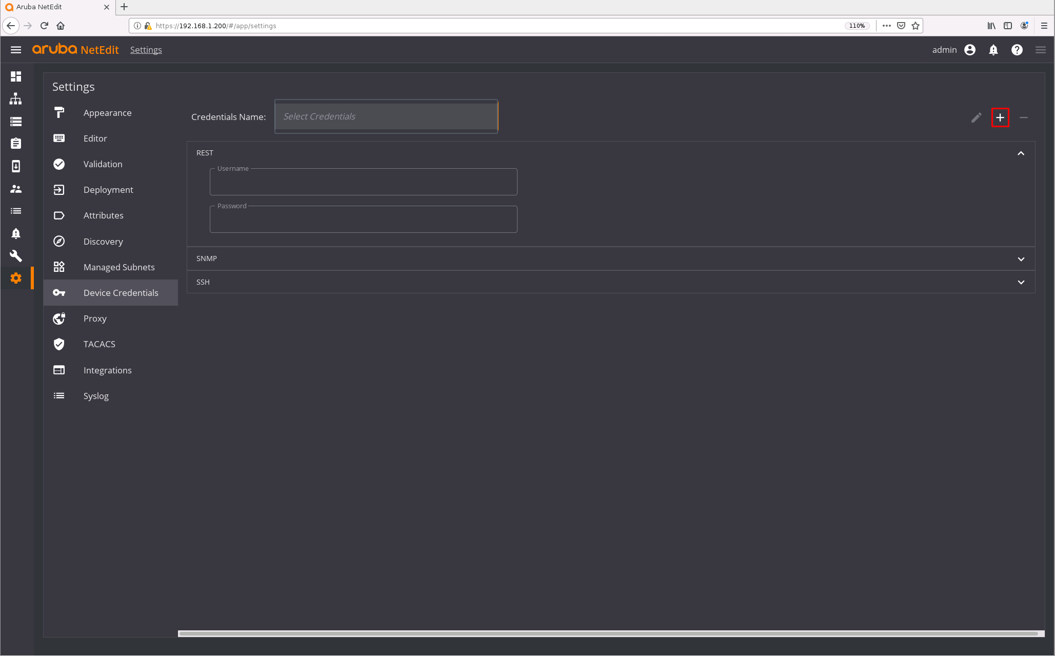
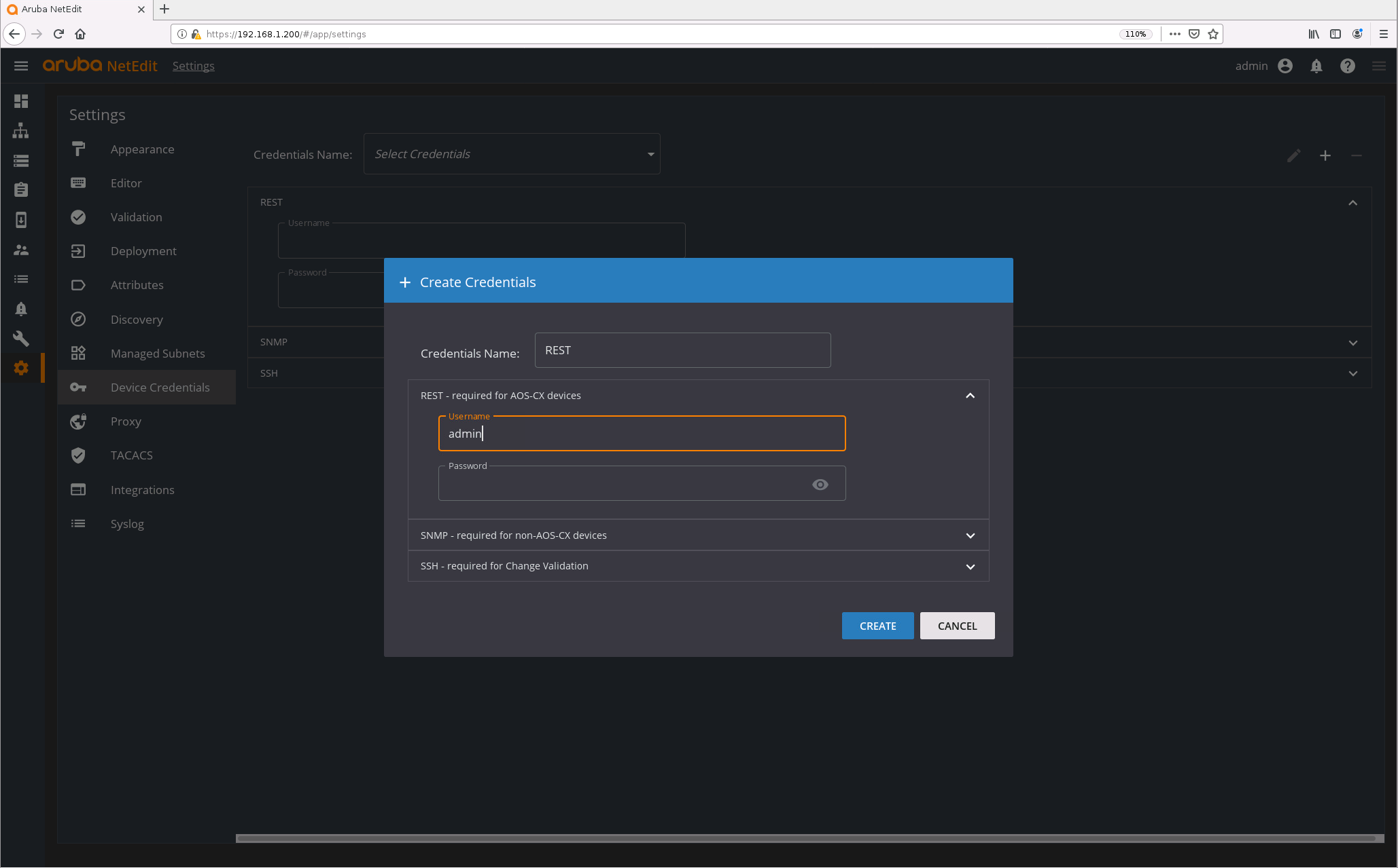
Give it a name and input the username and password for the REST credentials. Do not use the default empty password.
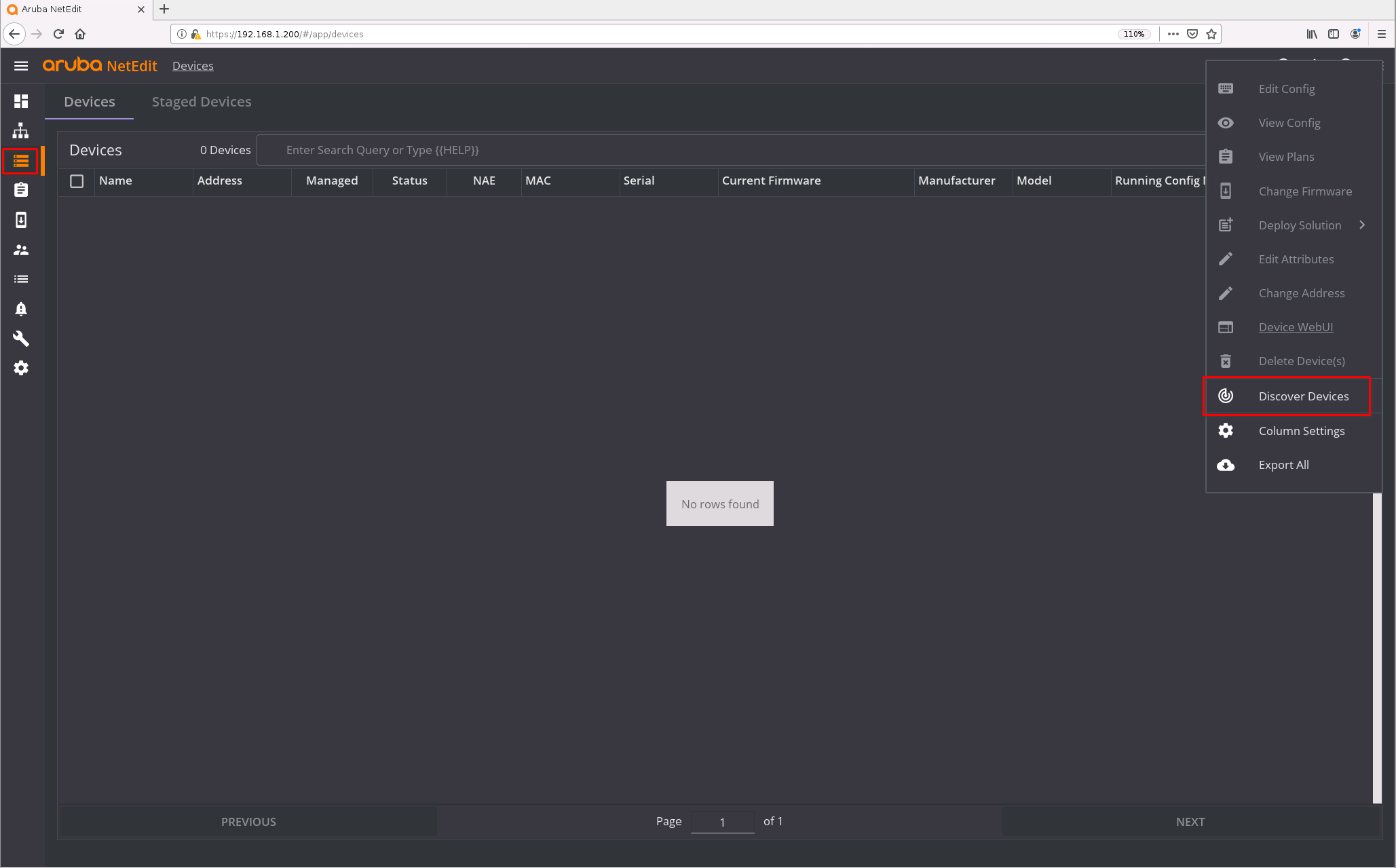
Great. Next, we need to discover the switches. Navigate to “Devices” and select “Actions” in the upper right corner. Here, click on “Discover Devices”.
Type in the network your switches are in, mine is 192.168.1.0/24, and enter a seed IP address. This can be one of the IPs of your switches.
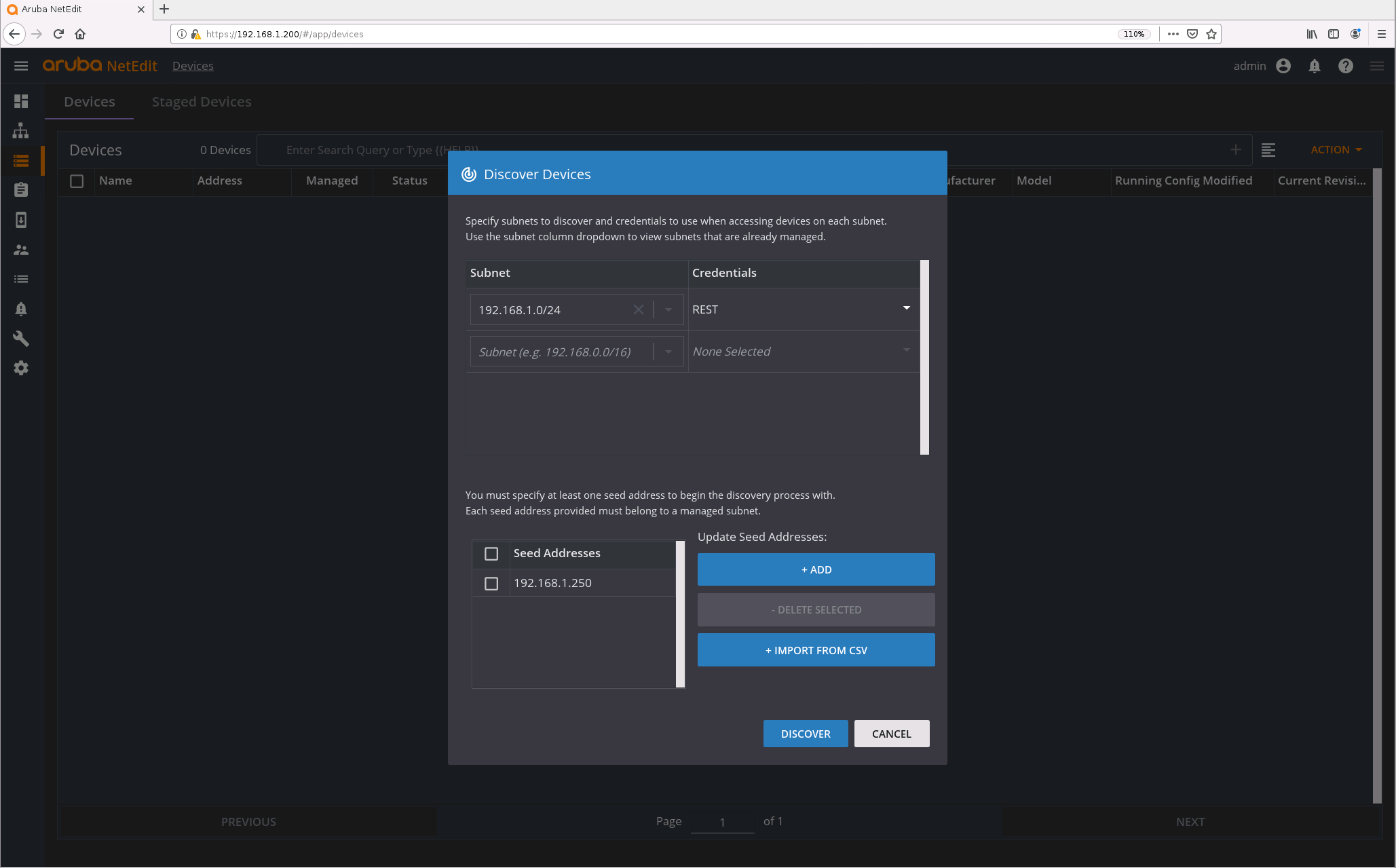
Now we wait.
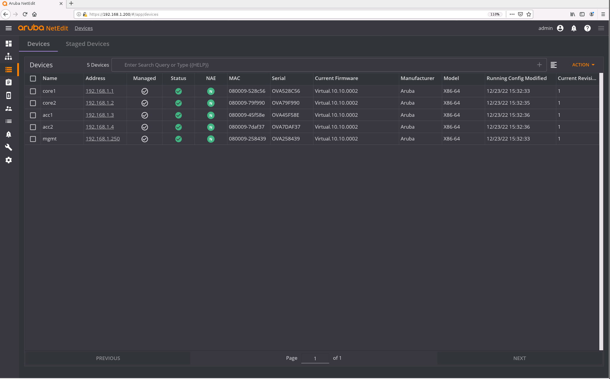
After a few seconds, the switches should show up. You can also check them in the “Network” tab.
Deploying configurations (multiple switches)
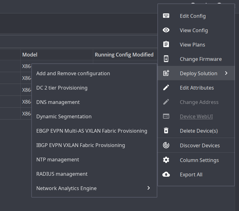
OK, let’s have some fun with the setup. I want to deploy a VLAN on all devices. For this, navigate to “Devices” -> “Actions” -> “Deploy Solutions” and select “Add and Remove configuration”. Enter a name for this new configuration. Add the config you want, in my case the VLAN 130 and a name for it.
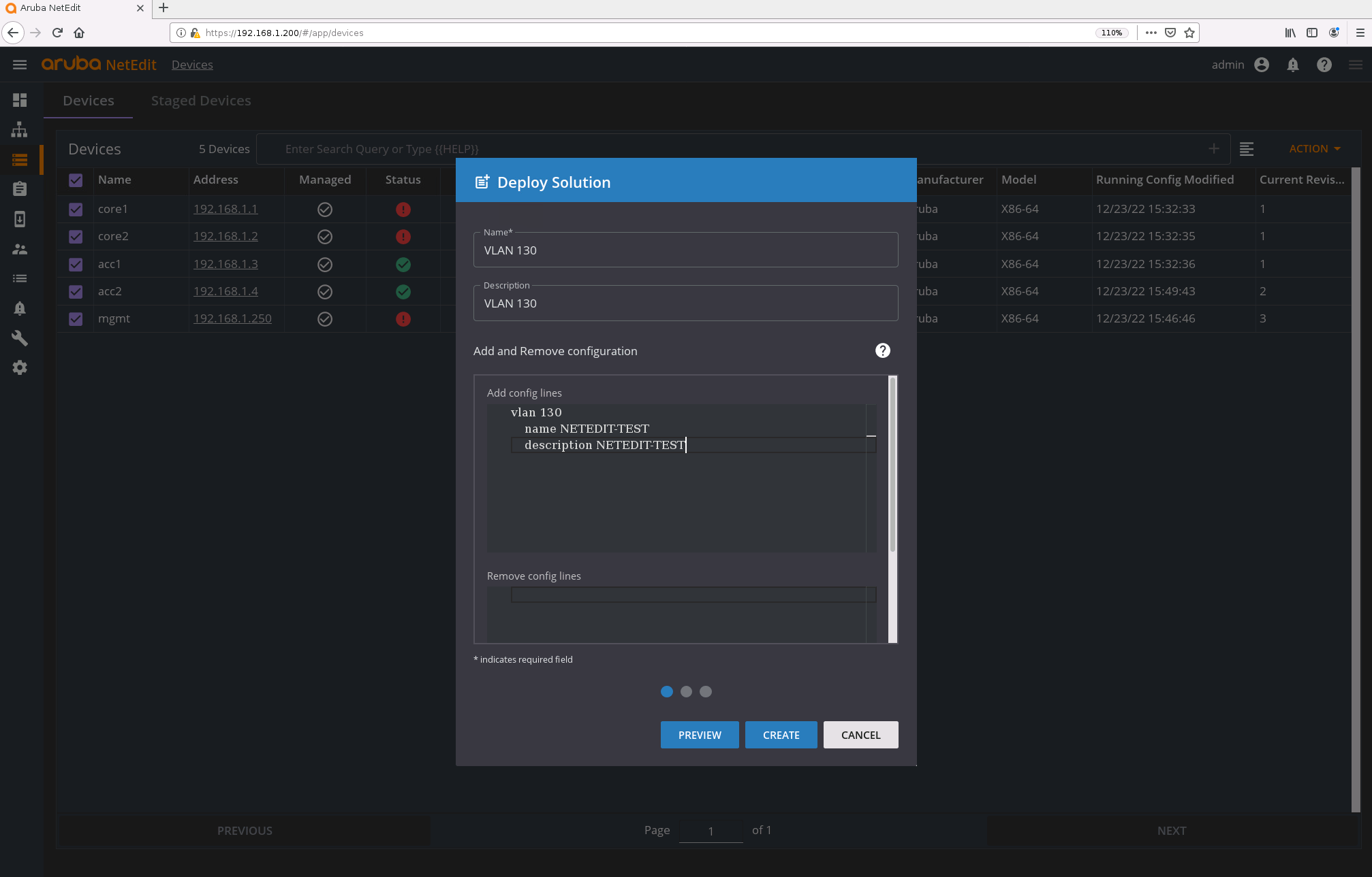
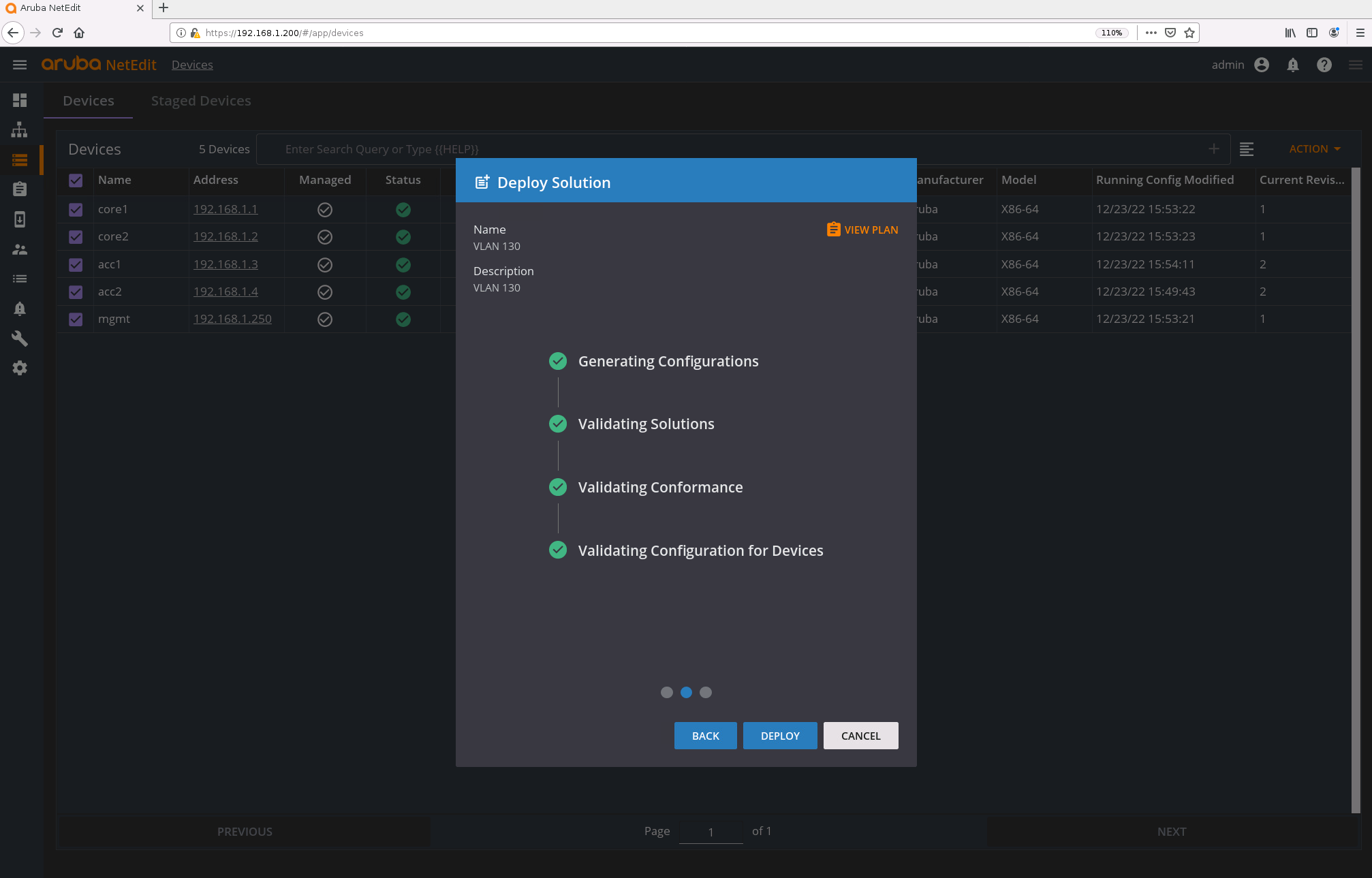
Click on “CREATE”. NetEdit will check the configuration and validates it for the switches. If you used an empty password for the switches, you will receive an error message here. Something like this.:
‘user’ must match ‘(.* group administrators .|admin .)’
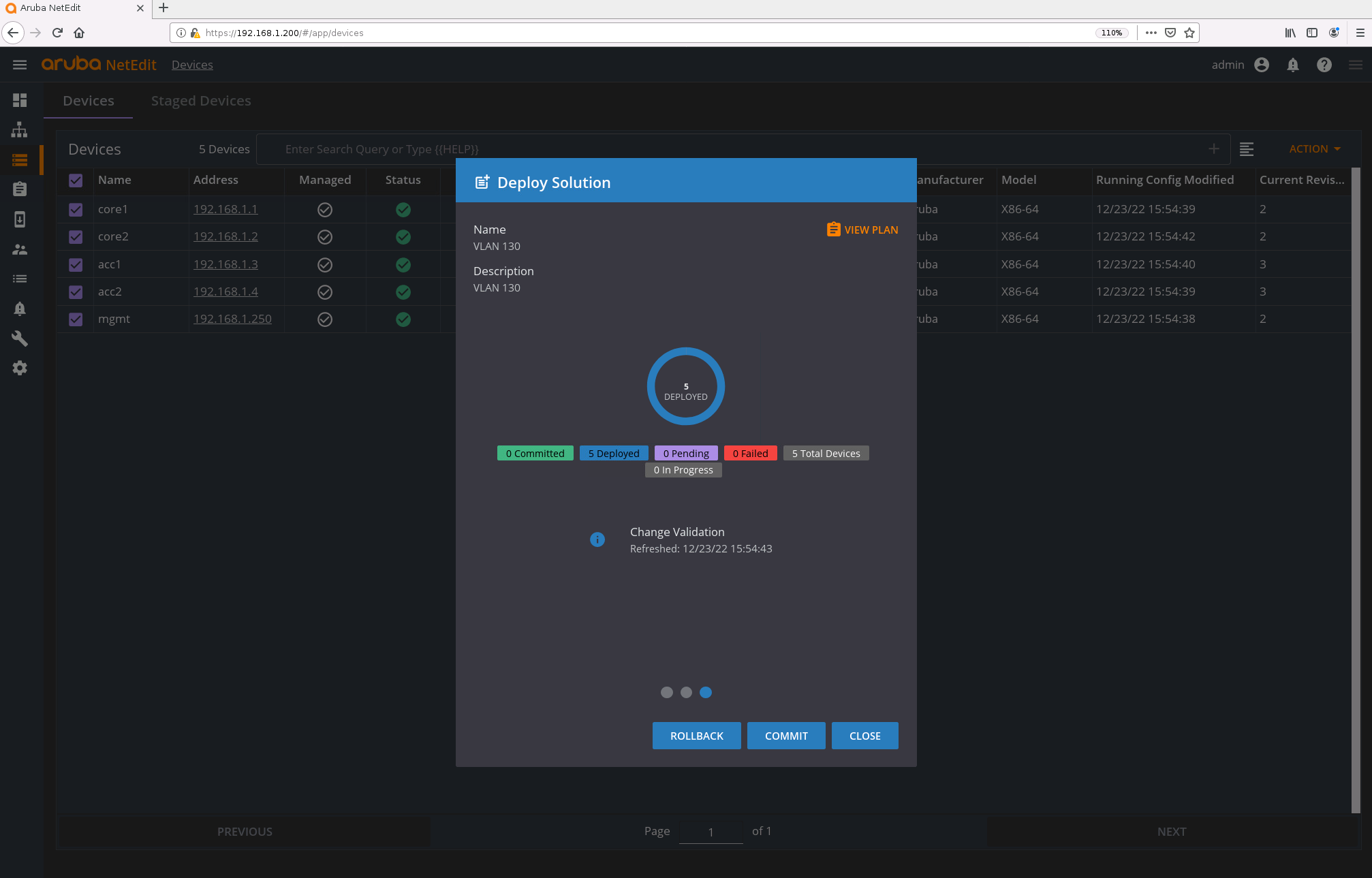
If everything is green, select “DEPLOY”.
If everything worked correctly, you can commit the config.
Let’s check the switches.
core1(config)#  show running-config
...
vlan 1
vlan 130
    name NETEDIT-TEST
    description NETEDIT-TEST
...
Great.
Deploy configurations (single switch)
Let’s do the same for a single switch.
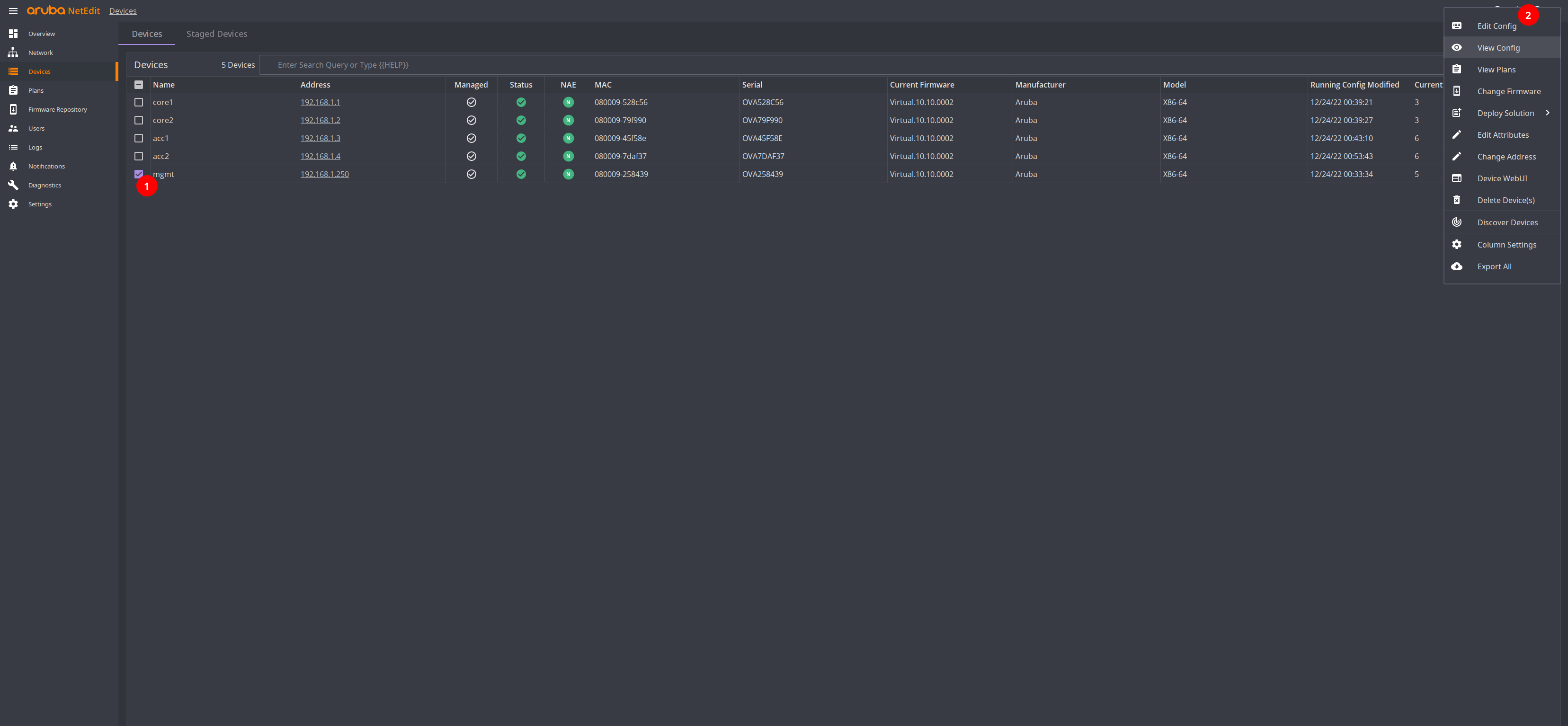
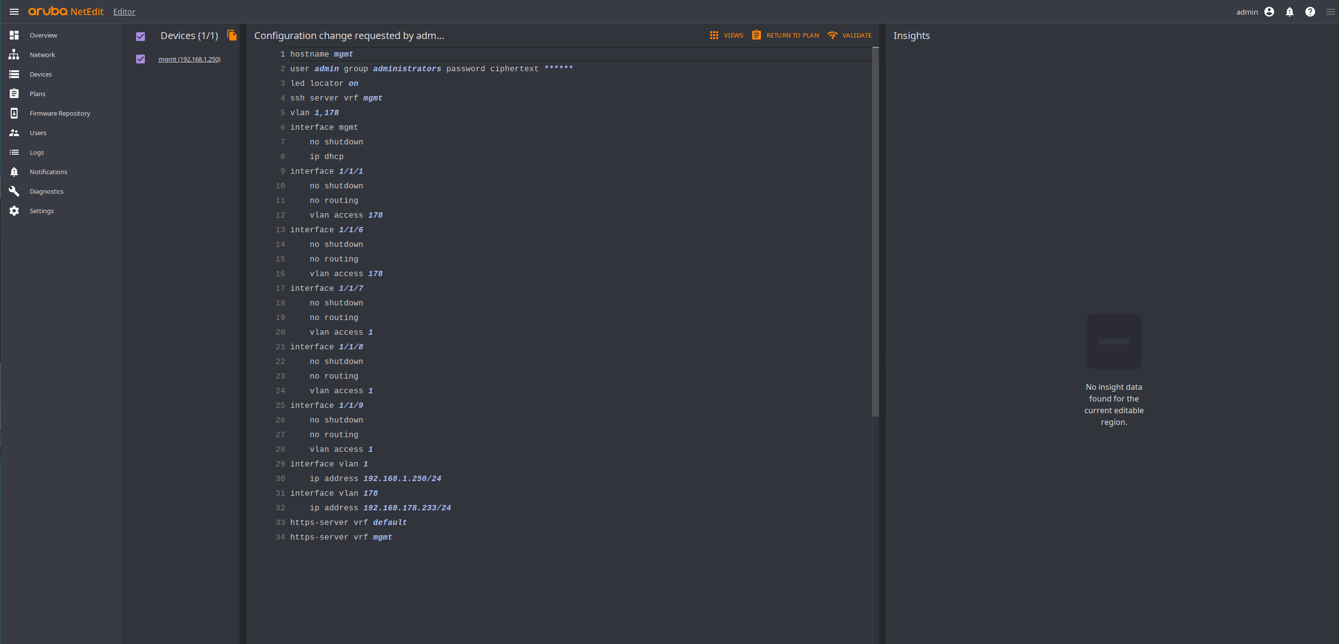
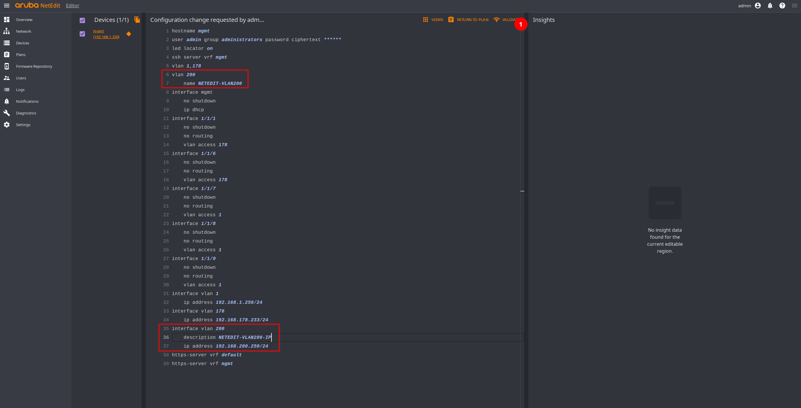
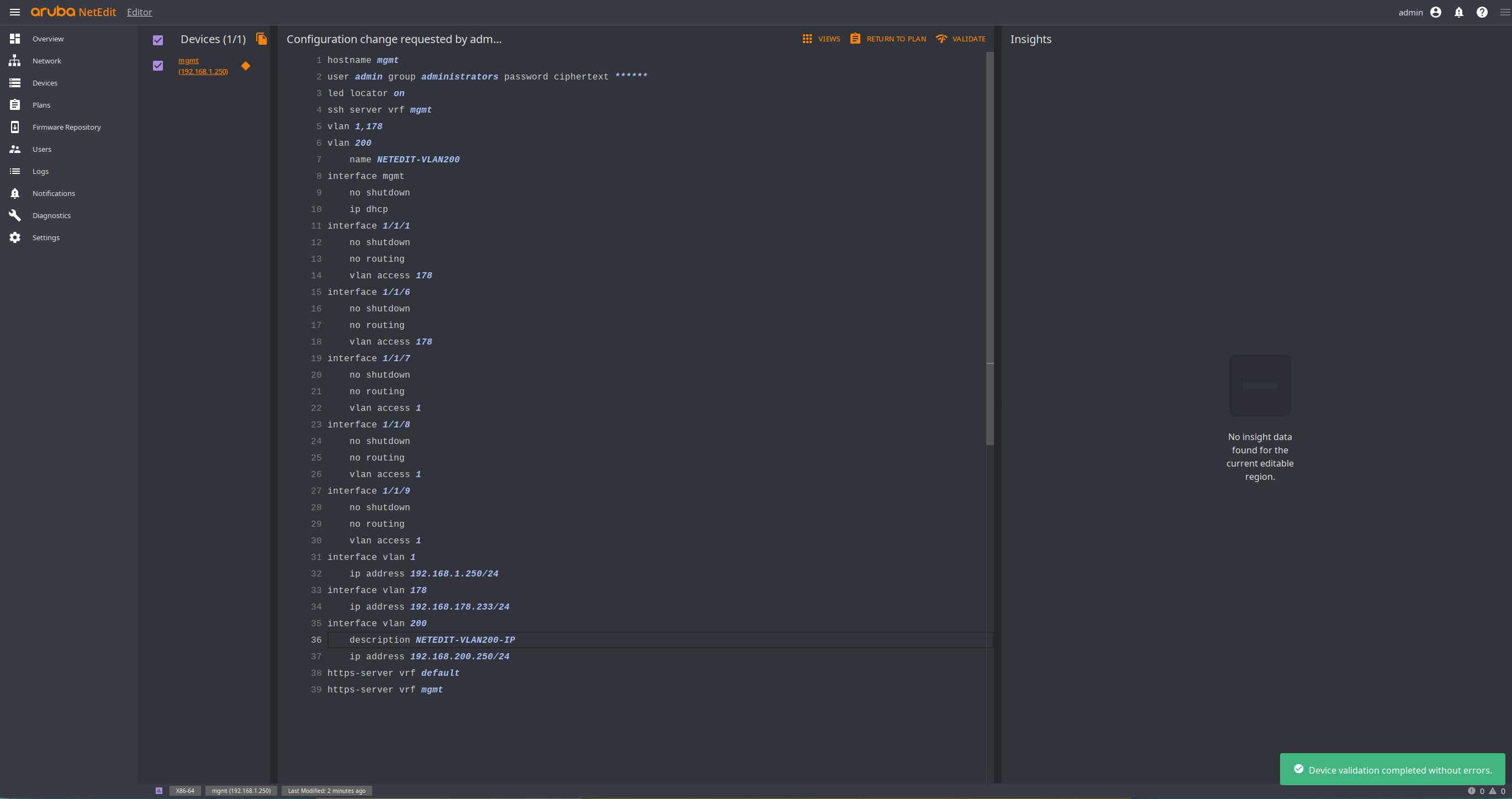
Select a single switch, I will choose “mgmt” and click on “Action” -> “Edit Config”. Here we can see the currently running configuration. I will add the VLAN 200 and give it an IP address.
NetEdit will move the configuration automatically to the correct position. Once we are done, click on “Validate” (1). If the validation is completed without issues, select “Return to Plan”.
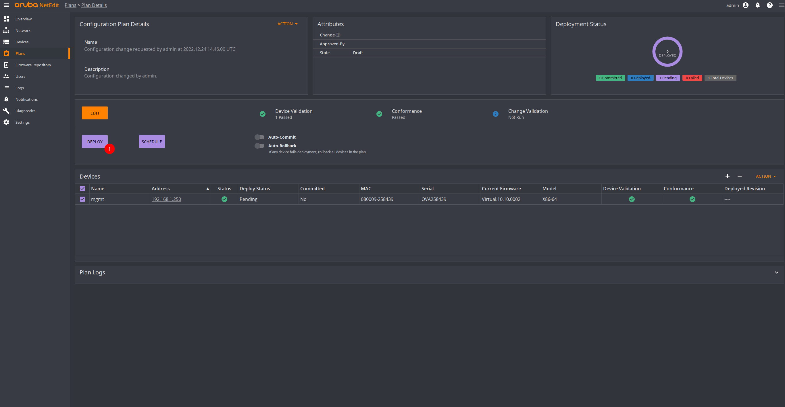
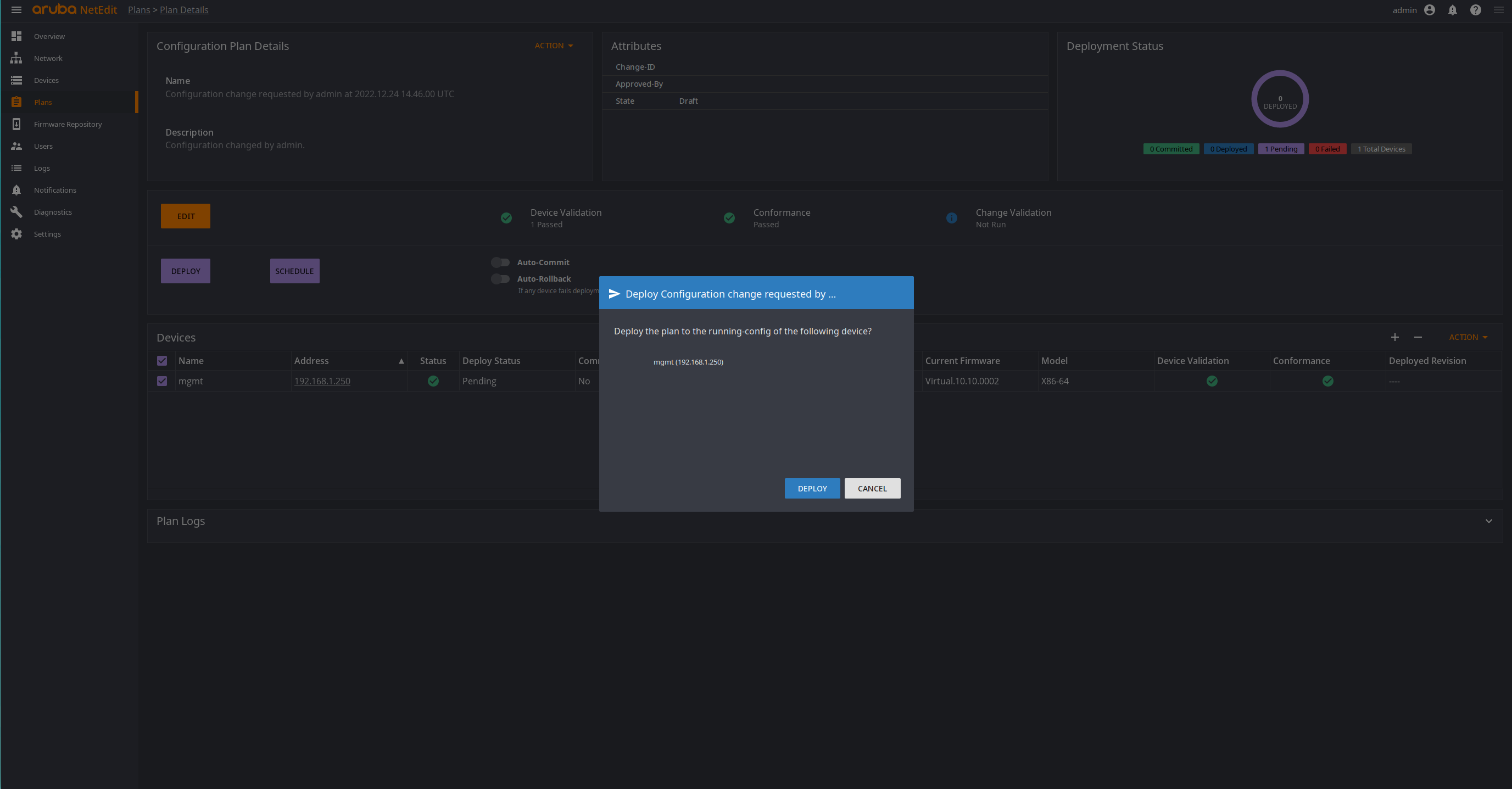
Here we can either edit, deploy or schedule the new configuration. I will deploy it.
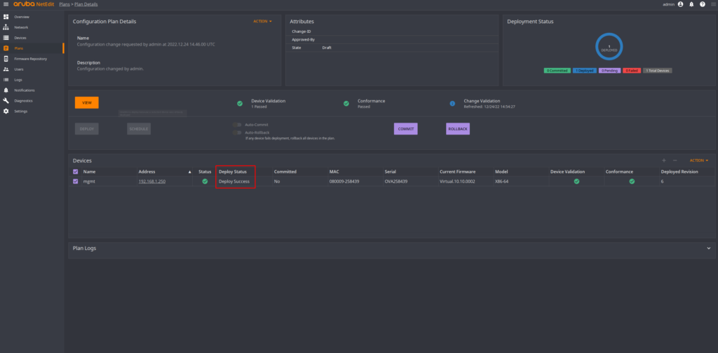
If everything worked out, we will see the “deploy status” as successful. The last step would be to “commit” the configuration, otherwise it won’t survive a reboot.
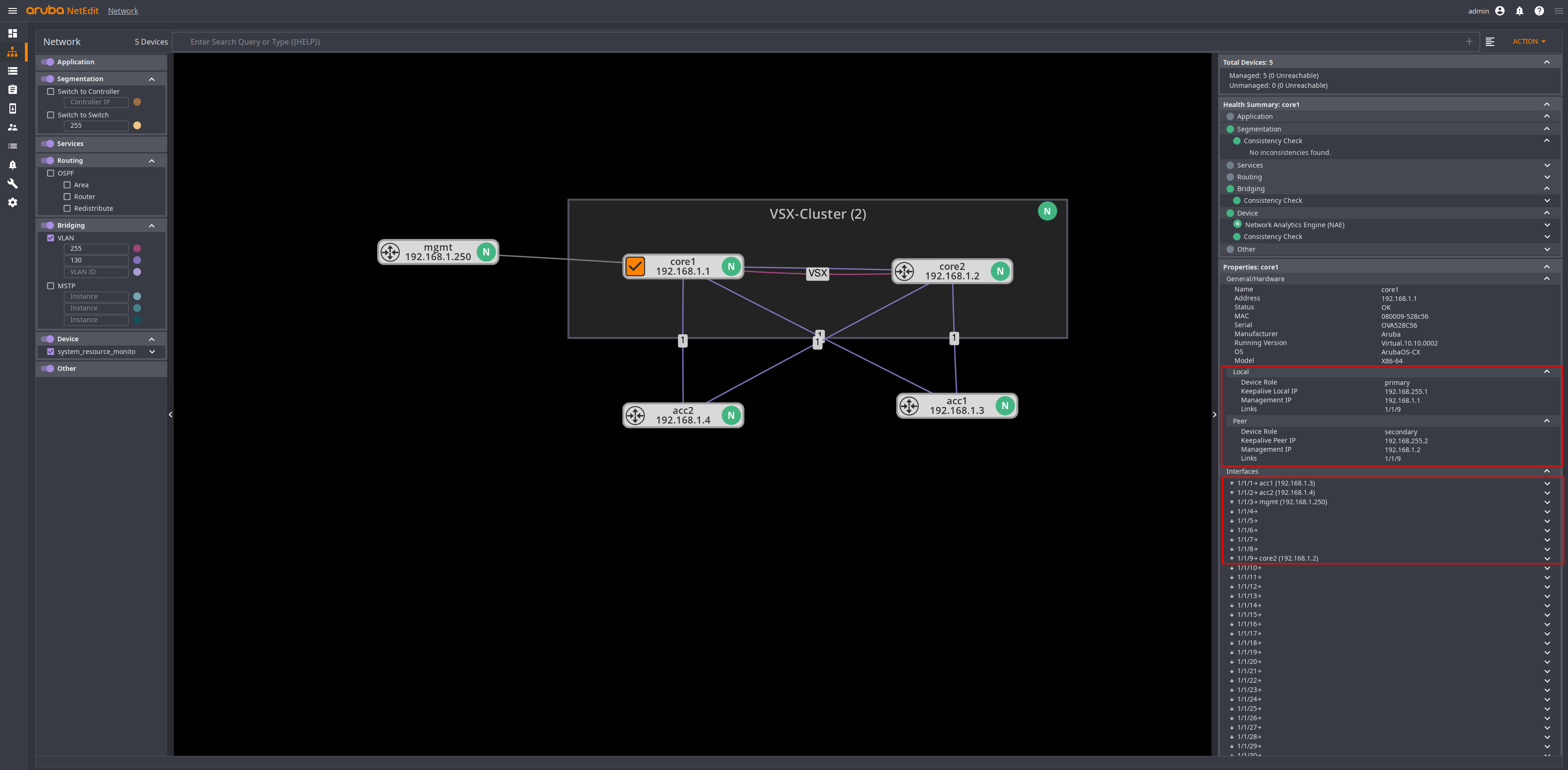
Switch Details (Network)
A few more features that, I think, are nice. Navigate to “Network” and select a single switch. Now we get a bit of information on the switch. Like the IP address and in the case of a VSX switch, the peer device, the link information per interface, and a health summary.
Let me demonstrate the health check. I will remove the VLAN 130 from the LAG on the acc2 switch.
acc2(config)# interface lag 1
acc2(config)# no vlan trunk allowed 130
Checking the WebUI.
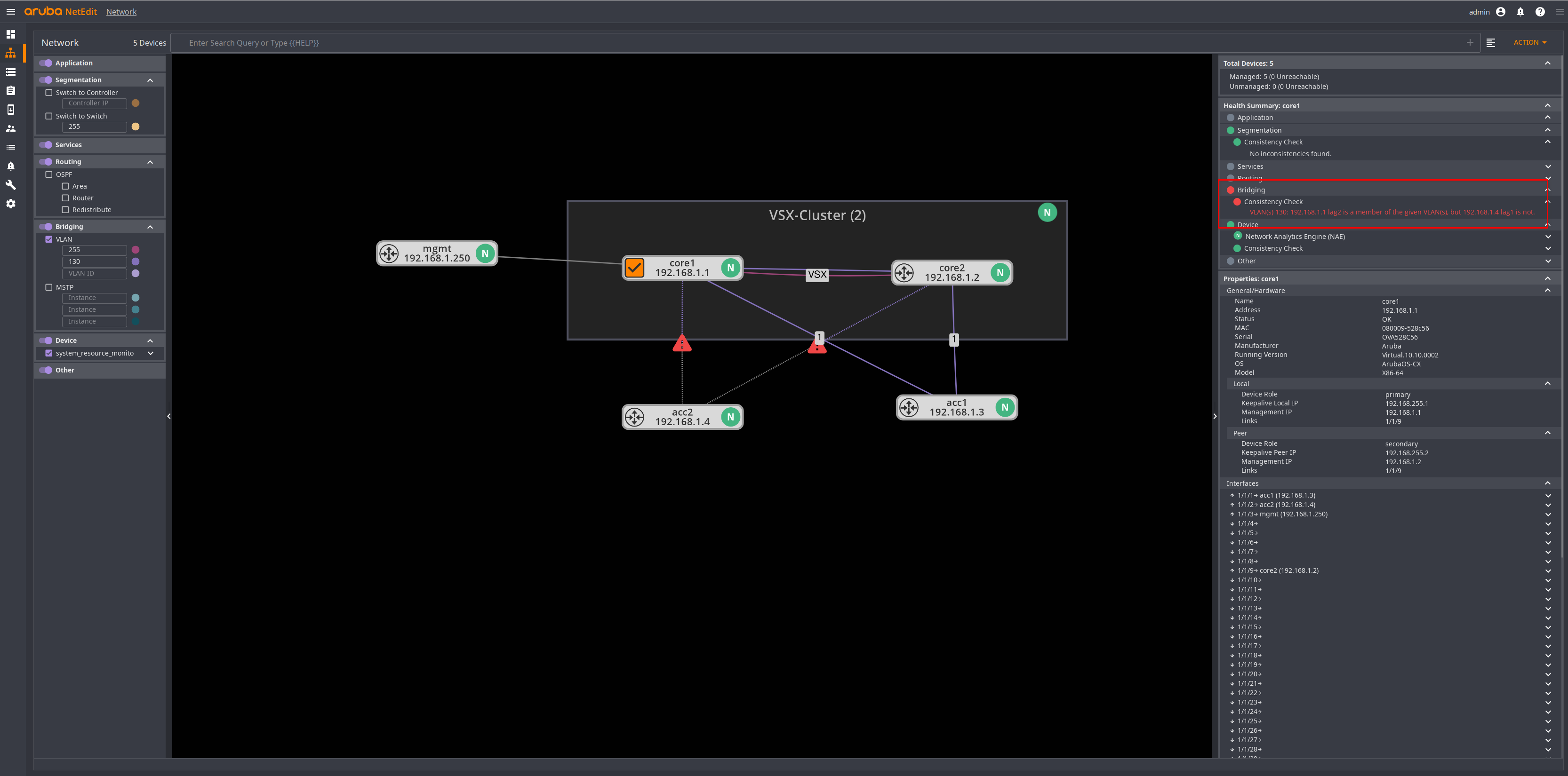
It took only a few seconds, and it already shows me an error. The reason for the message is, that we have VLAN 130 configured on the LAG on the core side, but not on the access switch. If we remove VLAN 130 from the core switch, the error will also disappear.
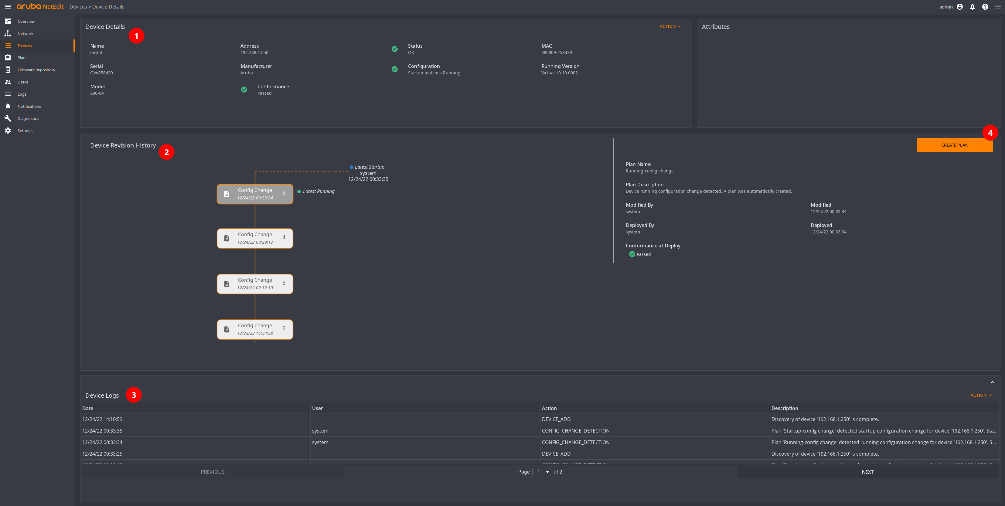
Switch Details (Devices)
Let’s go back to the “Device” tab. Here we can select a switch by clicking on the IP, where we get a bit more details. For instance, we have the device details (1), a history of the device configuration (2), and logs at the bottom (3).
On the right, we can create a new plan for this device (4).
OK. That’s it for now.
There seems to be an interesting feature that allows one to create a whole VXLAN fabric. Might try this some other time.
But, for now that’s enough. 🙂
Till next time.